
So far, all the instruments are either built directly into the EnsembleBot cabinet and master circuitry or attached as slave instruments through the CAN bus. We have a plan to make some small and simple percussive units, that we can place anywere in the room for a great, immersive surround-sound effect. Well, some kind of effect, anyway.
Instrument status: Under construction. Still in design phase.
RF VIRTUAL WIRE
More to the point, we want to make small units, each playing a single tuned bell using battery power and wireless control. Battery powered units are not rocket science, but designing an easily configurable, low-power wireless slave unit, that can actuate a noisy, inductive and power hungry solenoid, is more of a challenge.
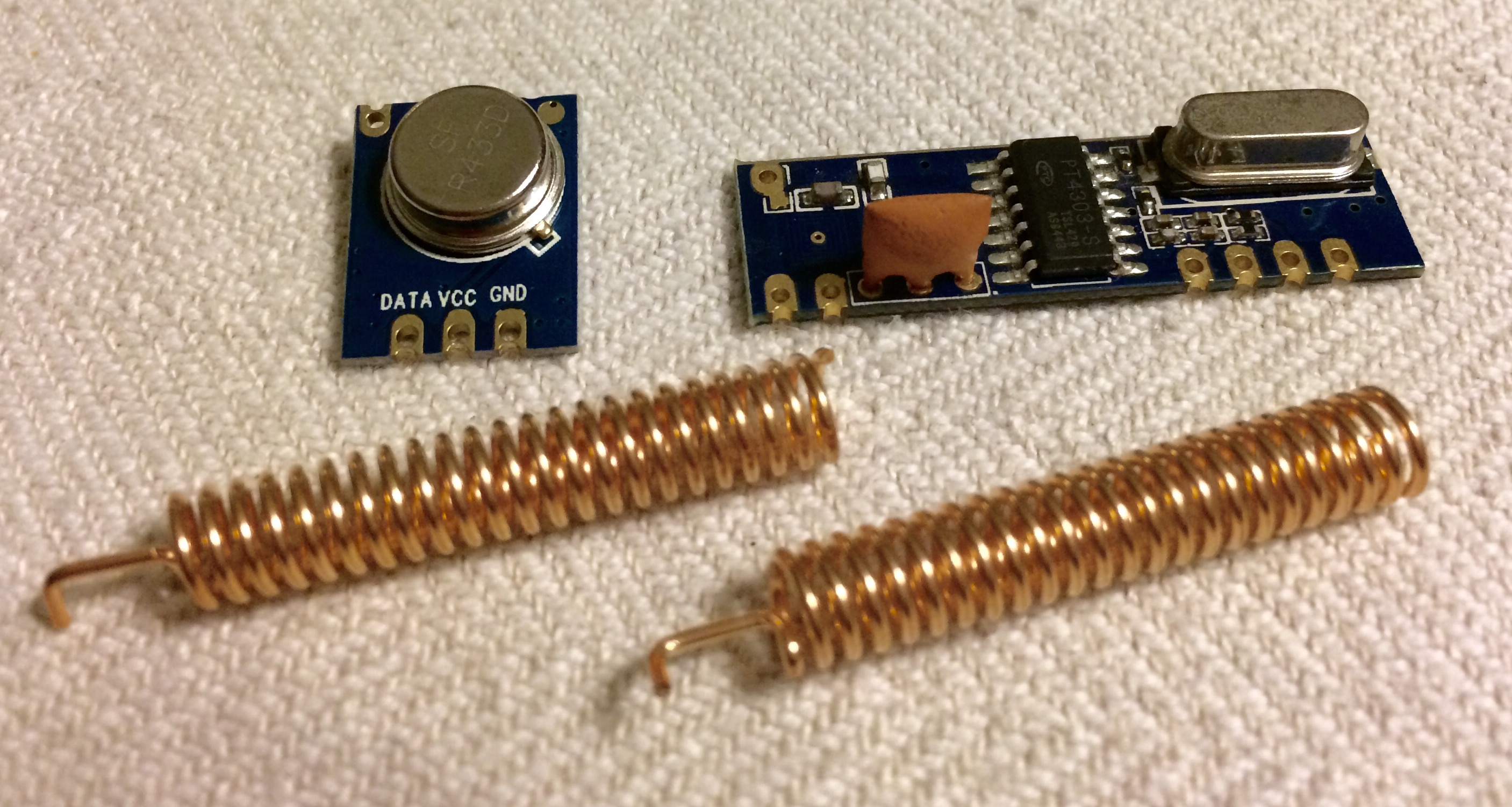
The backbone of this setup is the STX882/SRX882 radio frequency (RF) modules, They consist of a transmitter (the smaller module) and a receiver (the larger one).
These cheap devices use the 433 MHz frequency range to send and receive low-powered digital radion signals. Basically, what data a microcontroller sends to the transmitter, can be read from by another microcontroller from the receivers’ data output. A virtual wire library handles the communication, synchronized transmission, buffering, error checking and so on.
They are not small, powerful radio stations, and even with the small antennae attached, the range of reliable communication is measured in meters rather than tens of meters, and it’s more or less restricted to line-of-sight. But that’s perfectly fine for our use.
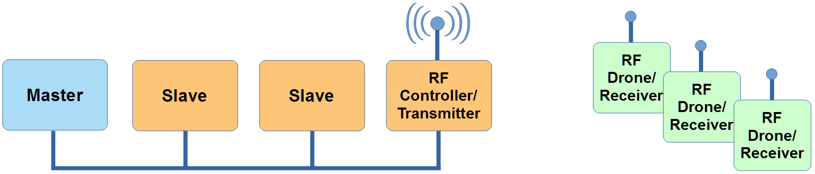
CONTROLLER / TRANSMITTER
The transmitter part will most likely be designed as a slave instrument, connected to the EnsembleBot though the CAN bus. IT will be a very simple box with a micro-controller (most like an Arduino Nano, or an even smaller ATtiny), a CAN-bus module, and a STX882 transmitter module. Maybe an RGB LED for simple status feedback. And that’s it. No B-side power. No moving parts.
All the controller needs to do, is receive EBP events from the master, put events onto a queue, and transmit simple messages to the drones in a timely fashion.
DRONES / RECEIVERS
The receiver parts (drones) are where all the fun happens. They are basically a number of identical, individual instruments, each capable of actuating a single solenoid to strike a tuned bell.
MICROCONTROLLER
Our initial plan was to base the drones on an ATtiny84A microcontroller. They are easy to work with, operate on very low power, and has plenty of programming space for this application. However, our prototype experiments showed, that it is not trivial to have an Arduino controlled transmitter and an ATtiny controlled receiver work seemlessly with the same communications library. We tried both VirtualWire and different versions of ManchesterRF, but none of them seemed to work well enough in this setup without ugly hacks to the libraries and/or board definitions in the Arduino IDE.
So, knowing from initial tests that the RF modules work flawlessly between two Arduinos, we decided to base the drones on ATmega328P microcontrollers instead. These are the same microcontrollers used in Arduino Uno and Nano, and so work with unmodified libraries. Surprisingly enough, the much more complex and powerful ATmegas are actually cheaper than ATtiny84As, and the power consumption is comparable. Also, with the ATtiny we would have had to design some more circuitry to compensate for the lack of I/O ports, but with the ATmega we have plenty of I/O and can reduce the circuit complexity significantly.
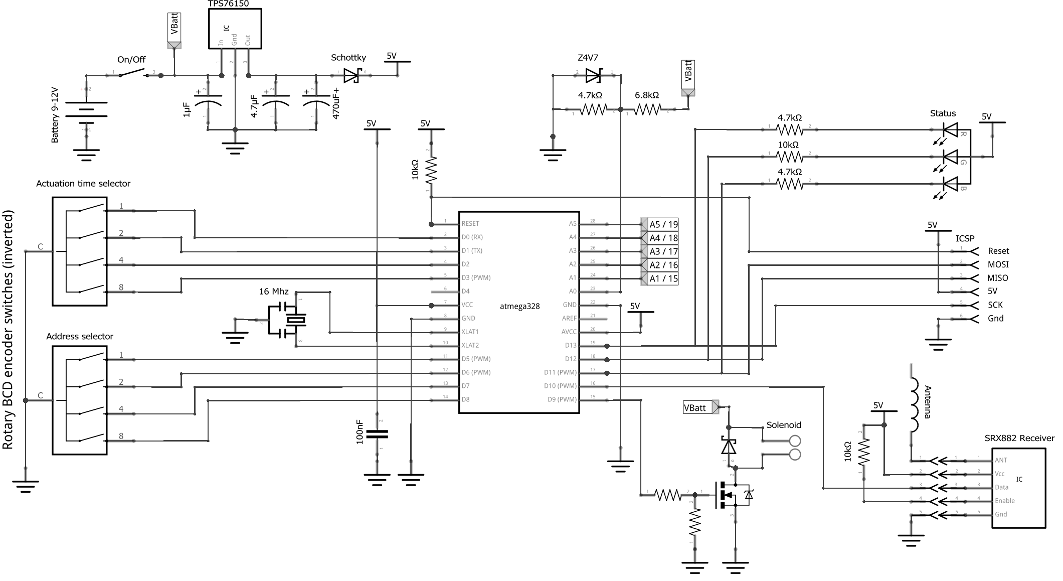
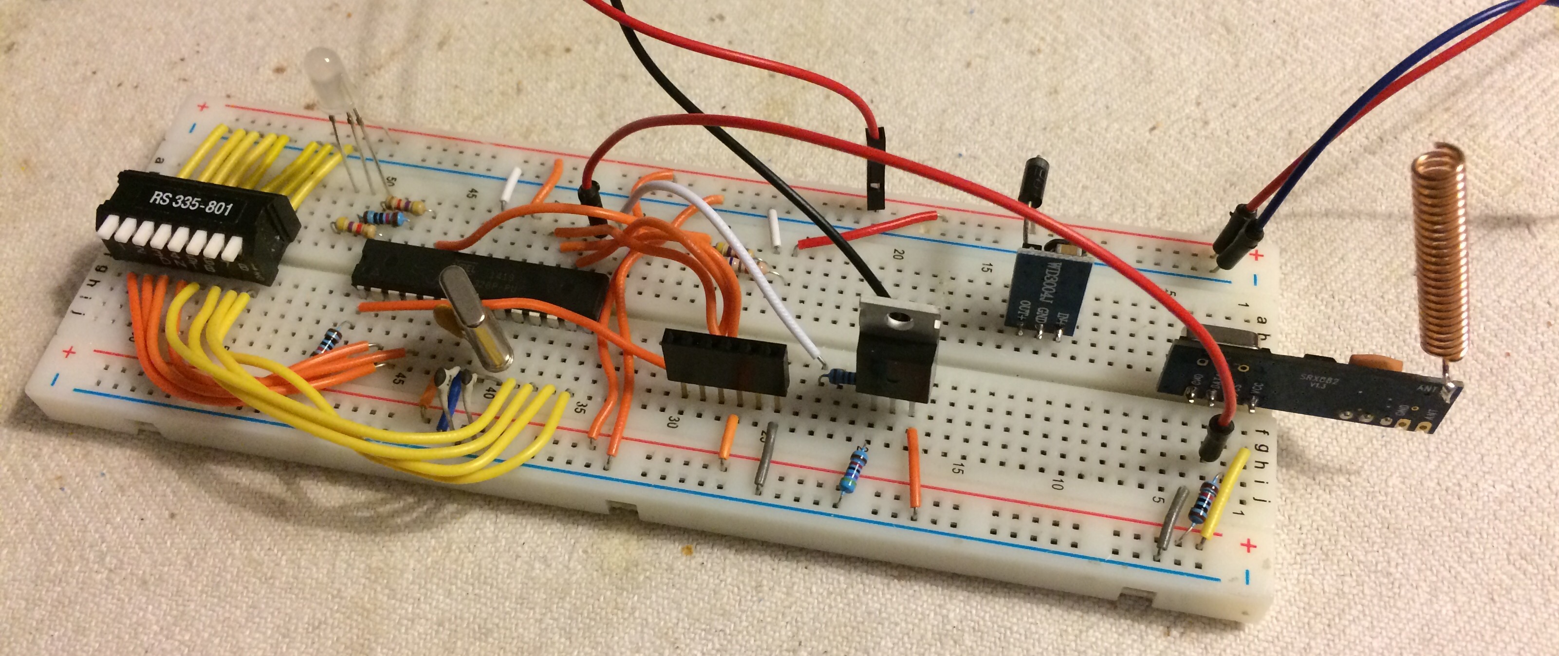
Above is our schematic of a drone, and below an early prototype of the drone circuit. The essential parts are of course the SRX882 receiver module, a MOSFET driver stage for driving a solenoid, and the Atmel ATmega328P microcontroller.
ADDRESSING
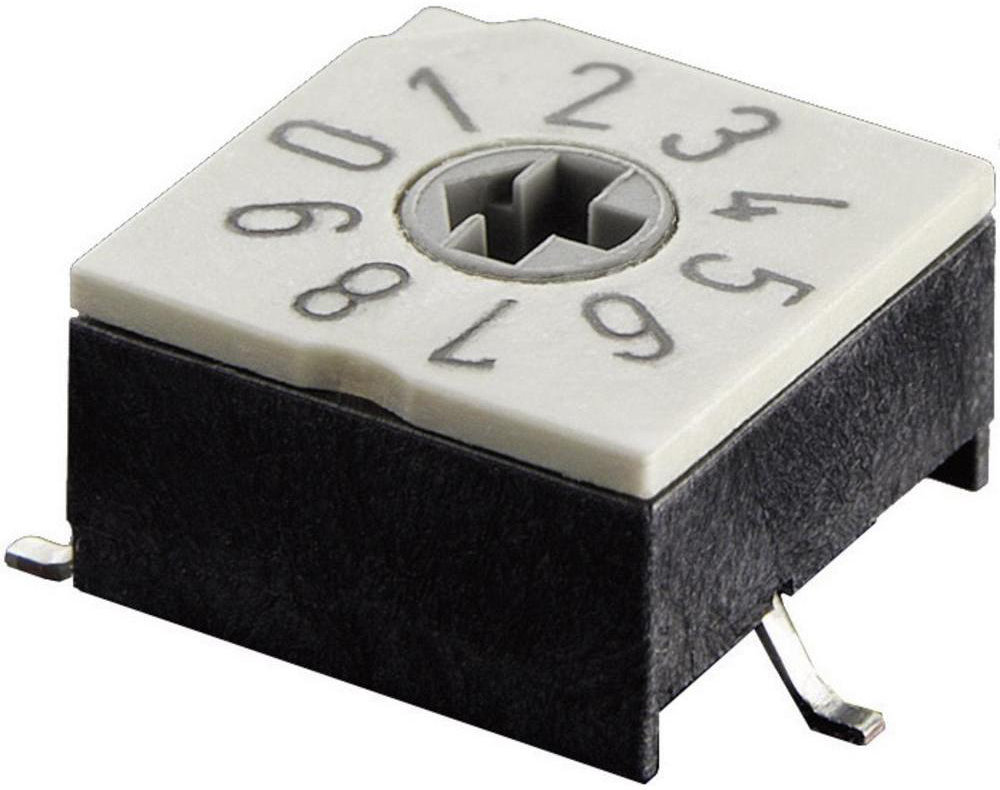
We want to have a few basic configuration options on each drone. To target a specific drone from the master/controller, there must be some way of differentiate the otherwise identical drones. Instead of hardwiring an ID or address into the circuitry, we use a small rotary switch (BCD encoder) to select an address value from 0 to 9.
SOLENOID ACTUATION TIME
The needed solenoid actuation time (i.e. for how long the electromagnet must be under power to move the steel rod with sufficient speed and force) depends greatly on the solenoid type, characteristics of the individual solenoids, and the actual physical setup, and so we need to be able to set an actuation time specific for each drone. Instead of sending an actuation time from the master/ controller, like MIDI note on/off events, it’s more practical to just hardwire it into the devices. So we’ll use another rotary BCD encoder like the one shown above to select between 10 different actuation times (eg. from 10 to 50 milliseconds).
This hardware setup also supports a hypothical future need for more complex actuation schemes. This could be a setting for receiving event-by-event actuation times to achieve some measure of dynamic percussion, or a setting for simple on/off, e.g. to control a dc motor or something else. But if the need arises, it could be solved entirely in firmware.
IN-CIRCUIT SERIAL PROGRAMMING
For prototyping we used an old-school ATmega328P-PU, which is a rather large 28-pin DIP package. Programming it without also including an FTDI chip for USB, the easiest way is often to put the chip into ZIF socket, program it using an AVR programmer, and putting the MCU back into the circuit. But in the finished design, we won’t be using this bulky version of the chip, but the much, much smaller version, ATmega328P-AU in a TQFP-32 SMD package. This chip cannot be easily removed once soldered in and won’t fit into any standard ZIF socket, but it’s only 7 x 7 mm, enabling a much more compact design.
So, instead we use in-circuit serial programming (ICSP), which is basically an external connection to the MCUs’ SPI and reset pins. If carefully designed, these pins don’t have to be exclusively reserved for ICSP. As seen on the schematic above, we also use the MISO/MOSI/SCK pins for the RGB LED. There are two advantages to this. First we can use the same I/O pins for more than one purpose, and secondly, the RGB LED will double as a visual feedback on SPI (ICSP) activity, i.e. an indication of the programmer actually uploading to the MCU. We’ve tested it, and it works just great.
POWER
The primary power source will be a battery pack, most likely 8 X AAA, as this makes for a nice compromise between size, voltage, current supply and price. We could consider adding a 5mm DC socket for external power (wall wart) to save battery, but it probably won’t ever be used, so why bother. A medium size schottky diode will take care of voltage selection (regulated battery power or 5V from external ICSP programmer) and power source protection.
The battery power source will be somewhere in the 9 -12V range. This is of course too much for the MCU and recelver module, so we insert a
voltage regulator. Instead of using a standard 7805-ish regulator, we thought of using a small switched mode step- down converter (or Switching voltage regulator “buck” ). In theory these babies should be far more efficient than linear regulators, but they have two serious drawbacks: noise and unknown minimum load current.
Switching voltage regulators do enevitably emit some E/M noise as it switches. Even though it is of a much lower frequency (perhaps 100 kHz plus/minus an order of magnitude) than the RF module (433 Mhz), there may be some bad influence on the receiver. If this turns out to be the case, we will have to sacrifice power efficiency for reception quality.
But a more tangible problem is the question of minimum load. For a switching regulator to work, it needs a minimum load current to regulate correctly, and this current may well be in the same neighbourhood as the expected total current of the logic circuit. If this is the case (and given the sparse information on our small buck converters, we simply don’t know for sure), then we won’t have any guarantee of a well-regulated power supply, unless we insert a passive dummy load (i.e. a resistor from Vcc to ground). This is just a waste of milli-amps.
So we are more inclined to use a linear regulator, and we choose the Texas TPS76150 5V/100mA in a SOT23-5 package. With a total logic current use (MCU + receiver + LED) of about 10 mA, the potential (though probably neglible) loss of effeciency is compensated by a reduction of high-frequency noise. The regulator has some quiescent current, but less than the switching buck.
Besides the required capacitors on the input and output of the voltage regulator, we place a relatively large reservoir capacitor (470 μF) on the output to handle transient brown-outs from the solenoid actuations when battery power is running low.
As shown on the schematic above we place a simple voltage divider attached to the voltage source and an analog input (ADC) on the ATmega MCU. This allows us to measure the approximate battery level, and give some kind of visual feedback through the RGB LED (i.e. red means “battery low”). The analog input is protected from overvoltage or spikes with a zener diode.
D E S I G N
The drones will be built into some small, cheap plastic boxes. There will be some cut-outs to access the two rotary BCD encoders, a hole for the LED, a power switch and a socket for connecting the (external) solenoid (or whatever). Inside the box, most of the space will be taken up by the battery pack, leaving only limited space for the rest of the circuitry.
The plan is to design the circuitry for SMD components and either etch the PCBs ourselves, or have the PCBs produced in China if the complexity is too high. By designing for SMD components, we can make the PCB very compact.
PROTOCOL
In the simplest scenario there is only one event to send: Actuate now! So, any message received from the controller/transmitter means exactly that. The minimal protocol will only need to contain the address of the drone (4 bits). The drone knows its own address by reading the BCD encoder switch setting at start-up, and if an incoming RF packet matches this address, the drone actuates the solenoid. So, in this case we only need to send one single byte. Now, as mentioned above, we want to prepare for future needs. This could be a setting, where the host/master/controller provides an actuation time to support more a dynamic playing style, corresponding to the MIDI velocity value.
Another future scenario also mentioned above were the support for a more flexible on/ off functionality, corresponding to NOTE_ON and NOTE_OFF events in MIDI and EnembleBot Protocol (EBP).

So, now we’ve come up with the above protocol consisting of one or two bytes per event.
EVENT BYTE
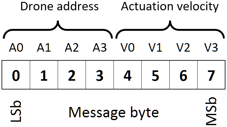
The first byte (the event byte) contains a 4-bit drone address (A0-A3). This is addressed as values 0x00 to 0x09, as this is the values settable by the drone BCD encoders. We could also prepare for a value 0x0F for “broadcasting” to all drones.
Next we have the UseNoteEvent bit (UE) that detemines if the drone should consider the packet itself as an explicit order to actuate (value 0), or if it should use the NoteEvent bit (E) to differentiate between NOTE_ON and NOTE_OFF events, thus ignoring BCD encoded actuation times and (optional) actuation times (velocities).
The NoteEvent bit (E) means NOTE_ON (value 1) or NOTE_OFF (value 0). If the UE bit is not set, this bit value is ignored.
Next the UseVelocityByte bit (UV) tells the drone if it should use the locally set actuation time from the BCD encoder (value 0) or use the velocity value supplied in a second byte of the packet (value 1).
The IsVelocityByte bit (V) tells if the current byte is a primary event byte (value 0) or a secondary velocity value byte (value 1).
VELOCITY BYTE
If the UseVelocityByte bit (UV) is set, the drone expects a second byte in the packet. The first 7 bits (V0-V6) are read as a velocity value in the 0-127 range. How these values are translated into actuation times, are note yet decided, but will likely read the BCD encoded actuation time setting, and using that as a maximum actuation time.
Finally the velocity byte has its own IsVelocityByte bit (V) just like the first byte, though here the value will by definition always be 1.
There is currently no way to address or identify different sets of drones, in case we want more than these maximum 10 units, and there is in principle nothing to prevent interference from other STX882 devices sending messages that could potentially be misinterpreted as a RF percussion packet.
ALTERNATIVE PROTOCOL
Now, if it should turn out, that we want a simpler protocol, either to conserve bandwidth (smaller message sizes), or if all the proposed complex functionality is superfluous, then we could consider a much simpler protocol.
In just one byte (8 bit) we can have 4-bit addressing and 4-bit (optional) velocity. This means that “message received” is interpreted as a NOTE_ON event, and the NOTE_OFF is timed by the drone microcontroller and defined by the hardware setting of actuation velocity or the 4-bit velocity value in the message byte.
Now, with this simple protocol we lose the option to send NOTE_OFF messages from the master/transmitter, and we lose some velocity resolution. And so what? So far, the RF drones are dedicated to hitting small tuned bells, and nothing else, and so we really don’t need any more functionality. And since the protocol is implemented purely in software (or firmware), we can always re-program the transmitter and drone receivers, if we need something more advanced down the road.
STATUS
[August 2018]
Tests show that the cheap STX882/SRX882 units are not up to the task. They are too unreliable, only works semi-reliably within a very short distance, and not at all when the solenoids of the EnsembleBot are activating. So, now we try experimenting with some nRF24L01 transceivers. They are small radio units operating at 2.4 GHz, interfacing with Arduinos through a standard 3.3V SPI bus. They should be a bit more resilient, though that will have to be tested. Potentially, we can use them bi-directionally, i.e. sending feedback to the controller. This could be used for some kind of generalized service discovery protocol.
Nevertheless, this means quite a setback in terms of both design, hardware and project progress.
Also, the market is flooded with cheap clones/copies of the nRF24L01 transceivers, and many of these knock-offs use quite a bit more than the rated 10-15 mA operating current. This will not do in this battery powered application. But we’ll see, when they arrive.
[February 2018]
Progress in this project has been slow because of our work on the PipeMare and PipeWind projects. But there is some small progress nevertheless. We have almost all needed components, except some better solenoids and the TCP76150 voltage regulators. PCB layout is progressing slowly.
[June 2017]
We have just built and tested a prototype drone using normal (through-hole) components and a breadboard.
We found that the bitrate is very low. The maximum reliable speed we measured were about 9600 bps. This is probably also dependent on the library and the MCU clock speed. Anyway, 9600 bps is sufficient, and even 4800 bps would be good enough. We also found that we need to insert a delay of 4-5 milliseconds between transmissions, apparently for them to be received correctly as separate transmissions by the receivers. This essentially means that if we were to order all possible 10 drones to activate at the same time, the orders will be sent over a certain period. A single protocol packet may take up to 5 ms to send at 9600 bps, and this means it will be 10 x (5 + 5) = 100 ms or 1/10 second to send them all. This delay will be barely noticeable, however, and the need to activate all drones at once will be a very special case and occur very rarely indeed, if ever.
We are starting to design the circuitry in EagleCAD, but the actual PCB layout awaits the arrival of plastic boxes and battery holders, as these two components will dictate the dimensions and placement of all other components.
In the meantime, we will begin “building” and programming the
controller/transmitter.
Next: Read about our ideas and plans for future instruments
Hi there.
Very inspiring page you have here.
I am in the early stages of creating a ceramics clay pipe organ – i was inspired by Look Mum No Computer on youtube, who bought a chruch organ and midi-enabled it.
I am located in copenhagen. I saw your website was .dk. Are you in DK as well?
Wow! “Look Mum No Computer” just blew my mind! I’m going to binge-watch those videos soon. Yes, we’re located in København as well. Tell me more about your clay pipe organ project – that sounds like a VERY cool idea.