
Robro is the nickname for our robotic Dobro guitar. It’s a very ambitious project, and even though we’ve been working on it for more than 3 years, it’s still not finished. Both mechanically and programmatically it presents a neverending list of challenges. Even though the tubular bells were the first finished EnembleBot instrument, the beginning of the Robro project predates all other instruments by several months.
Instrument status: The concept has been proved, but the instrument needs massive reconstruction of some mechanical parts and redesign and reprogramming of the entire controller
FROM DOBRO TO ROBRO
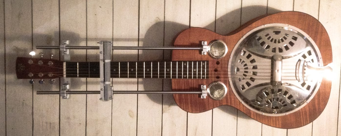
A Dobro is a resophonic (or resonator) guitar, and our model is a square-neck for lap steel playing style. Instead of using fingers to press the strings against the frets on the neck like a “normal” guitar, this is played by sliding a tone bar (or “steel”) up and down the neck. The strings are tuned in an open chord, so whereever you place the steel, you’ll get a clean chord.
If one absolutely must make a robotic guitar, a dobro is probably the easiest choice. All the neck-work is done by moving a simple piece of steel along a one fixed direction.
The Robro project can be divided into three parts:
- The neck/steel assembly: This is the part that moves the steel up and down the neck in fast but very precise movements.
- The pick/mute assembly: We use servo motors to pick each of the strings, and special rotary solenoids to mute/dampen the strings.
- The EnsembleBot slave instrument controller: It takes some nifty hardware and firmware to control all the mechanical parts, listen for and receive MIDI/EBP messages from the host/master, and translate them into mechanical movements.
THE NECK / STEEL ASSSEMBLY
Below is an early picture of the dobro, where the construction had just begun on the sliding function to move the steel tone bar up and down the neck. The steel is fixed in a “sled” that is moving along twin guiding shafts. The shafts and ball bearings are standard parts used in e.g. 3D printers.

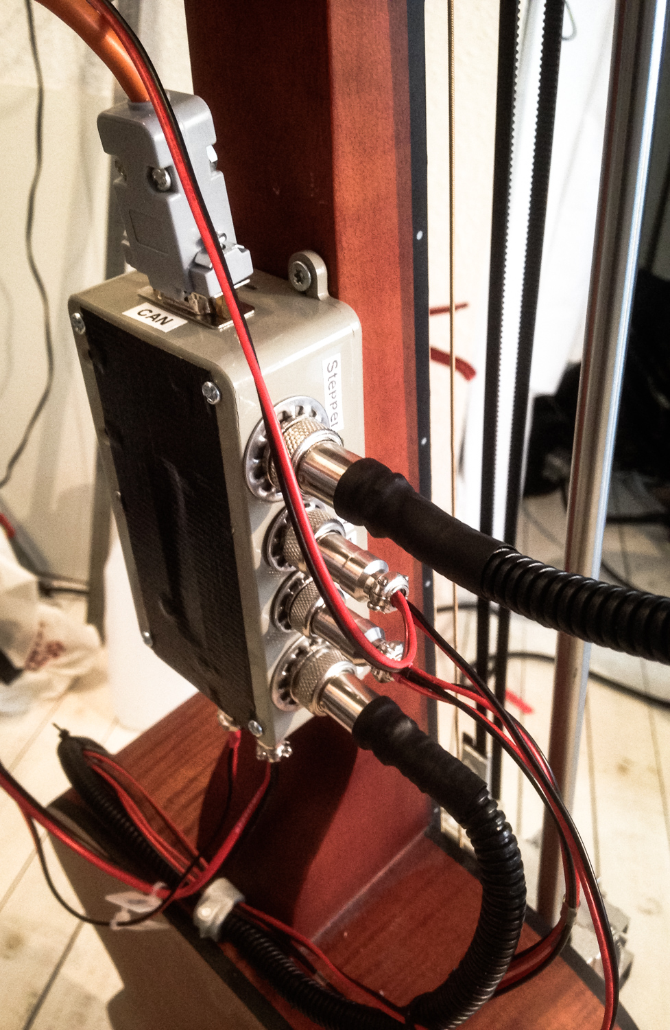
The steel slider is moved using a strong 12V stepper motor (a Nema17 42BYGHW208 to be precise) and a standard GT2 timing pulley belt loop. The motor is placed close to the head of the guitar on a springloaded platform to keep a uniform belt tension and to reduce mechanical stress in an otherwise rigid setup.
The driver for the stepper motor is a Pololu DRV8834 break-out module. Since the motor is placed relatively far from the instrument controller box, we found it best to place the driver close to the motor. The driver is mounted in a small plastic box, and to avoid overheating, we placed a small DC cooling fan inside the box. The fan is independently controlled by an Atmel ATtiny85 micro-controller, a Dallas DS18B20 temperature sensor, and a TTL-level MOSFET to switch the fan on/off.
Mechanically the system works surprisingly well. It’s precise and although not moving at lightening speed, it’s fast enough. The biggest problem is mechanical noise. The motor itself isn’t particularly noisy, but combined with the sliding ball-bearings and a spring loaded steel bar sliding along 6 steel strings on a guitar body that is specifically built as a resonance chamber to amplify sounds – well, let’s just say you can hear everything that’s happening.
Now, in that example, it’s worth mentioning that some of the noise stems from bad accelleration/decelleration of the steel, resulting in a distinctive KRRR! sound at the beginning and end of each movement. In the next version of the Robro controller we’ll use the stepper driver functions to move in combinations of full-, half-, quarter- or eighth-steps, or even lower.
To detect and react to extreme extreme steel positions we’ve placed micro-switches at each end of the neck. They are activated just before the slider reaches the end of the line, and is detected as a (software) interrupt by the controller.
The down-neck switch (i.e. the one close to the head) is also used at power-on initialization to calibrate the steel position in relation to the switch position.
THE PICKS
The steel slider location changes the pitch/chord like the left hand of a guitar player, but to pick/pluck the strings to make them sound off we need another mechanism to replace the right hand. The bluegrass way of picking dobro strings is using finger picks like modern banjo players use. That won’t work here.
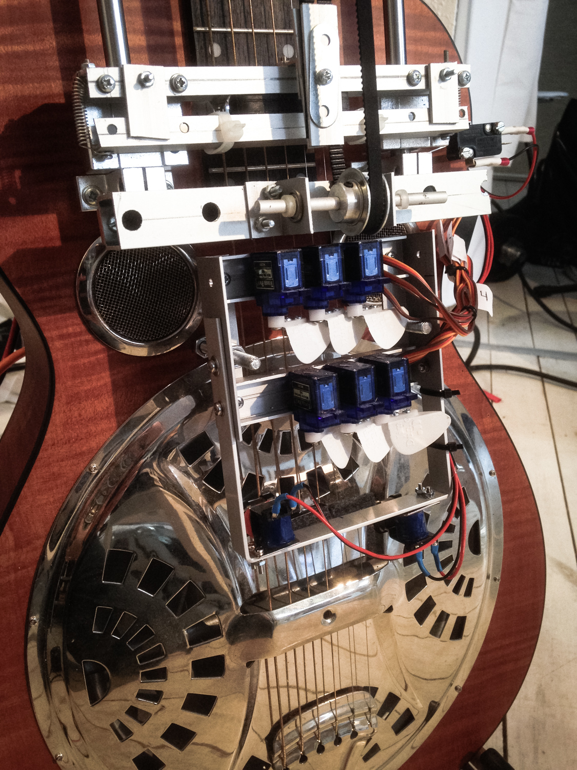
Instead we have placed six micro-servo motors with soft guitar picks mounted on the servo horns. That way we can pluck each string independently and repeatedly by swinging the pick from side to side:
The servo latency is acceptable, but the precision and reliability of the whole assembly leaves much to be desired. This is something we need to look into.
MUTES AND TUNING
Normally, a lap dobro is tuned in open G major in two octaves, with the strings tuned to G-B-D-g-b-d. Moving the steel enables us to shift the G chord to other chords, but we are still restricted to major chords. That is fine when playing bluegrass or German schlager music, but not good enough for us. So, we re-tune the strings to G-Bb-D-g-b-d, giving us a major chord and a minor chord.
Now, playing one chord, e.g. a major chord, and then switching to play a minor chord, will inevitably cause both chords to chime at the same time, albeit not equally loud. Also, the mere action of sliding the steel or picking other strings will draw sound from the “wrong” strings. This is called sympathetic resonance, and despite its sympathetic name, it should be avoided. This led us to design a muting system.
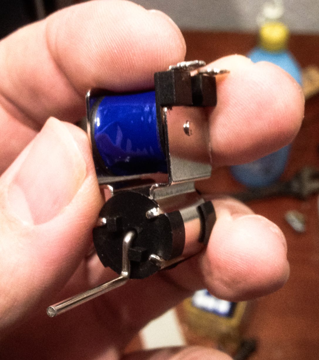
We can’t mute strings individually, but by string groups, i.e. the major chord strings and the minor chord strings. This is done suing a small rotary solenoid.
A linear solenoid, like we’ve used them in several of the EnsembleBot instrument, can move a shaft forcefully in one direction, and it’s the same direction no matter the polarity of the driving current.
A rotary solenoid is a different beast entirely. They turn a small arm 90 degrees in one direction, and keeps it there, even when the current stops. Reversing the current makes the arm move back 90 degrees. Reversing the current is easily done with an H-bridge motor driver like the classic L293D or the more efficient SN754410.
We’ve glued a piece of soft felt to the arm to better mute the strings, and then we have a simple but functioning mute system.
CONTROLLER
The hardware was (and still is) a tough nut to crack, but the controller electronics and firmware proved no less problematic. One of the reasons were that we tried to cram too much stuff into too little space.
But for several reasons, we may have to re-design the entire controller.
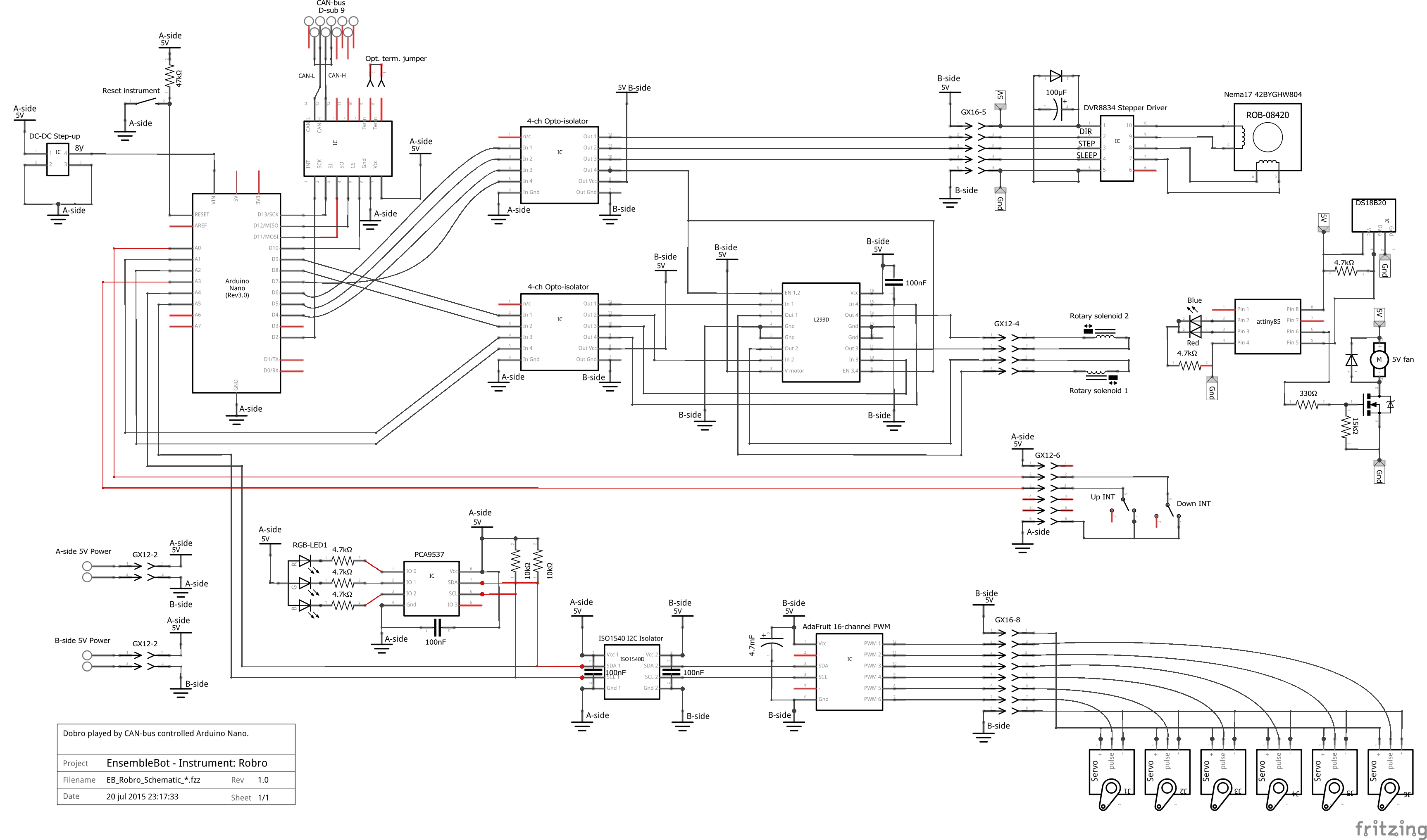
Our little, grey plastic box held:
- Microcontroller (Arduino Nano)
- DC step-up converter
- MCP2515/TJA1050 CAN-bus module
- Texas ISO1540 I²C isolator
- 2 x 4-channel optocouplers
- PCA9685 16-channel PWM driver for the pick servos
- SN754410 H-bridge for the rotary solenoid mutes
- 7 external connectors (A-side power, B-side power, CAN-bus, interrupt switches, servo controls, mute controls, and stepper controls)
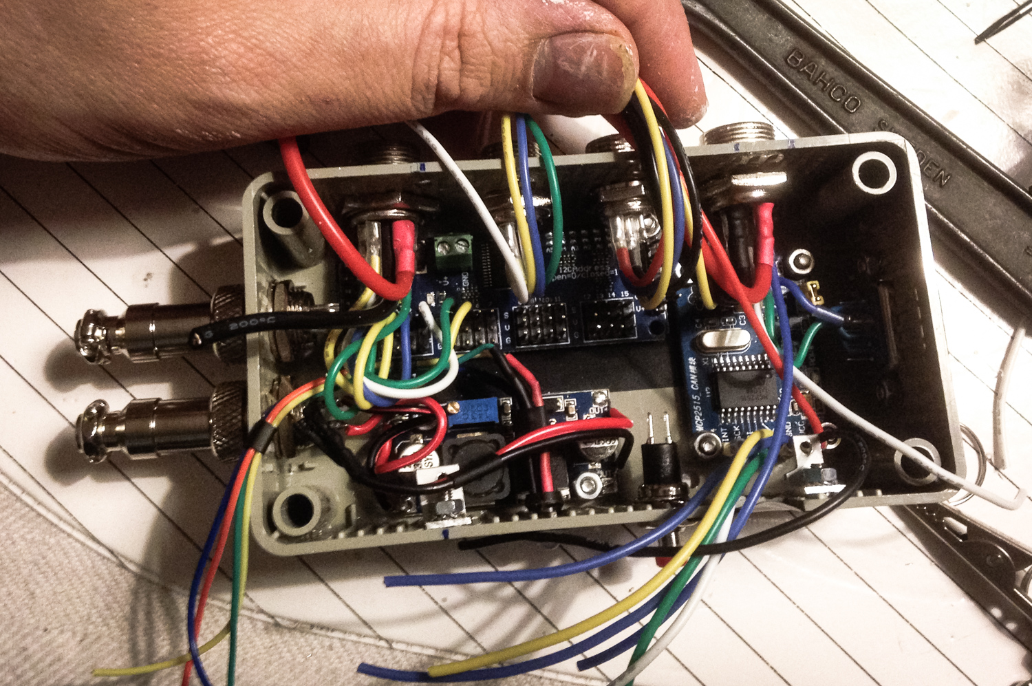
This compact design was very neat when assembled, but did indeed introduce a lot of problems. First of all it’s not very serviceable, which of course isn’t a problem when everything works. But it also means that it’s very hard (or impossible) to make changes to the controller.
As an example, the control signals to the DRV8834 stepper motor driver are limited to sleep/wake, direction and step. After working a bit with the instrument, we would like to be able to use the half-step and quarter-step functions for smoother and more silent movement. However, there are no more available I/O ports on the Arduino, and no available optocoupler channels nor the space for more. Just adding these extra control signals mean a complete redesign of the controller box is necessary.
EBP / MIDI CONTROL
Controlling an organ or a drum is pretty straight forward in MIDI and subequently in the EnsembleBot Protocol (EBP). It’s just sending NOTE_ON/NOTE_OFF events. The Robro is more difficult to control, since it hase three different things to control: The six individual picks, the steel slider position, and the two string mutes.
It’s easy to assign different MIDI notes to different events – one per pick servo, one per mute, and one per fret position for the steel – but representing this in some kind of practical and legible score is not exactly easy. So far, we use a customized TAB notation, but it’s very hard to work with.
FIRMWARE
The brains of the instrument is a small Arduino Nano. This is an easy to use micro-controller, smaller in size than the Arduino Uno, but with more or less the same specifications (and limitations). That means 16 Mhz clock, 2 KB SRAM and 22 digital I/O ports.
The controller manages CAN bus communication via SPI, EBP protocol parsing, interrupt handling from the steel slider boundary switches, PCA9685 servo control via I²C, H-bridge control for the mute solenoids, control of timing, position and accelleration/decelleration for the steel slider stepper motor, and finally a single RGB LED for basic status feedback.
CALIBRATION AND CONFIGURATION
The highly mechanical nature of this instrument means that there are a great many things to calibrate precisely to ensure a smooth operation. The pick servos need to know at which PWM duty cycles their two extreme positions are, the mute solenoids need to know their required actuation time, but most importantly the precise positions of the guitar neck frets and the initial position must be measured out, mapped and converted to motor steps.

All these parameters can change slightly over time or with adjustments to the hardware. Instead of hardcoding them directly into the firmware and uploading a new compilation each time we make small, incremental parameter adjustments, we build in support for setting the parameters directly from the host computer using MIDI SYSEX messages.
When the Robro controller receives such SYSEX messages, it stores the values in the micro-controller EEPROM, so it remembers the new setting.
MISSTEP WOES
The controller has quite a lot of tasks, but in theory not too much. However, we do indeed experience some persistent but irregular problems.
The stepper motor suffers from “mis-stepping” and after a while the steel starts to overshoot its target positions, tripping the boundary interrupt switches and causing an instrument shutdown. This may well be a result of the Arduino Nano not being fast enough to handle all these concurrent tasks. The stepper, especially, requires timing in fractions of milliseconds to run smoothly, and when having to manage all the other tasks at the same time, the timing will be off and the stepper starts to stutter and miss steps.
These task handling timing problems are aggrevated by the CAN bus EBP handling, as activity intensifies in the entire EnsembleBot. All CAN messages are broadcast to all nodes on the bus, and each slave node receives the messages, parses them and determines if they are for that particular slave instrument or not. So, when many instruments are playing, the controller needs to evaluate a lot of messages. In these situations we experience frequent instrument errors and in some cases blocking of the CAN bus, stopping the EnsembleBot entirely.
But why is this not a problem on the other EnsembleBot slave instruments? Well, none of the other instruments are as timing sensitive as the Robro, and that makes all the difference.
WHAT NOW?
So, how do we solve these timing issues? One way could be to write more efficient firmware, e.g. by using interrupt controlled timing. But rewriting all device libraries and optimizing every line of code is a bit beyond our desires and skills. That leaves us with the coice of microcontroller and/or controller architecture. As we see it, we have two options: Upgrading to a faster microcontroller, or distribute tasks to parallel microcontrollers.
FASTER MICRO-CONTROLLER
This would be the easy way out, as almost all code and hardware would be re-usable.
There are many faster micro-controllers out there. In the PipeDream61 we use a Teensy 3.2 (72 Mhz), in the PipeMare controller we use a Teensy 3.5 (120 Mhz), and the PipeWind v.2 pressure monitor has an STM32F103C8 “Blue Pill” (72 Mhz). The Teensies are by far the easiest to work with as the PJRC “teensyduino” plugin for the Arduino IDE comes with a wide library support. The Blue Pills are a bit more difficult to work with, and it can be quite troublesome to find working libraries for simple things like basic hardware I²C support.
But where e.g. a Teensy 3.2 costs around £20 plus shipping, a Blue Pill costs only £3.40 including shipping. Also, the Blue Pill has 32 directly accesssible GPIO ports, where the Teensy 3.2 only has 24 GPIOs (and 10 less accessible GPIOs). But that is not really important, since it’s more than the Nano’s 20 GPIOs.
However, we have no guarantee that it would actually solve our problem to just upgrade to a faster microcontroller. The timing won’t change and the number of incoming CAN messages will be the same, but we will have some more clock cycles to do stuff between each event.
MORE MICRO-CONTROLLERS
Another more complex, but in the end more reliable solution, would be to use more microcontrollers. One way to do it would be to see them as two separate and independent slave devices, each connected to the CAN bus. But that wouldn’t solve much.
Instead, we could isolate the timing sensitive part (i.e. the stepper control) to a controller of its own, getting simple orders from a central controller. The secondary (steel) controller could be set up as an I²C slave device.

In this configuration the primary (slave) controller would parse EBP events from CAN bus, and control the picks and mutes through the PCA9685 PWM. In the earlier schematic shown above we controlled the SN754410 H-bridge for the mutes using I/O ports on the Arduino, fed through optocouplers. There’s nothing to prevent us using some of the unused ports of the PCA9685 as basic TTL outputs, and this way we free up at least five I/O ports and optocoupler channels.
When the primary controller receives CAN messages that translates as a new steel slider position, the request is sent via I²C to the secondary controller.
The secondary controller only has two jobs: Listen for I²C commands from the primary controller, and control the position and motion of the stepper motor. Without other tasks and irrelevant interruptions from the CAN bus, there is no reason to use anything other than a simple, cheap Nano as controller.
This solution sounds like both the most robust solution and the most interesting. But it does introduce a small challenge. As mentioned above, we use MIDI SYSEX messages from the host to set and store hardware configuration parameters. With two controllers, the parameters are also split between two controllers. We can’t communicate with the secondary controller through EBP/CAN bus, so what do we do?
We could place a shared EEPROM module on the I²C bus (e.g. an Atmel AT24C256 module), but that could very well introduce some collisions, if we didn’t inform the secondary controller to keep quiet for a moment while the primary controller updates the EEPROM, and then inform the secondary controller, that it needs to refresh its parameters from EEPROM. That sounds like trouble.
A much easier solution is to make the primary controller just relay the parameter updates to the secondary controller, and let the secondary controller store it in EEPROM and take any action required.
We need to plan some kind of protocol for the primary/secondary I²C communications, and learn how to program Arduinos as master and slave, but that is a minor hurdle.
STATUS
[June 2018]
There is still much to do, before we have a functionable and reliable robotic guitar. This is also why we can’t present a full demonstration of the instrument yet, even though the Robro was our very first instrument project.
But we have a road map. We need to redesign and rebuild the controller, and we also need to redesign and rebuild the pick/mute assembly.
Next: Read about the EnsembleBot percussion instruments