
The tubular bells were the very first completed instrument in the EnsembleBot. It all started with a small wooden cabinet and the discovery that cheap steel tubes (clothes hanger cabinet rods) could be made to make nice sounds.
Instrument status: Finished and working
THE CABINET
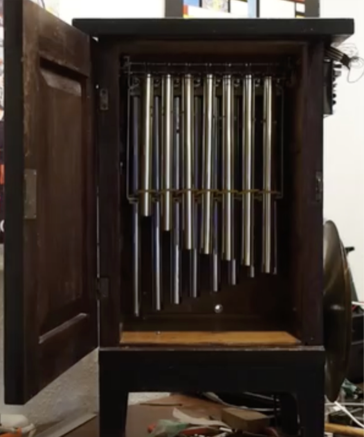
To start ourselves off building EnsembleBot instruments, we needed some kind of frame or container. This little wooden cabinet was a good start. A bit small, but practical (and free!). It was almost immediately decided to place a set of tubular bells inside, and so the design could begin.
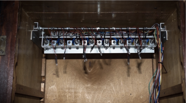
To get the controller circuitry and the MOSFET/solenoid bell drivers out of the way, most of the electronics was placed on the backside of the cabinet. This means the electronics are visually out of the way, yet easily accessible.
Apart from the tubular bells and the percussion circuitry, the cabinet also hosts the glockenspiel (on top of the cabinet), cymbals and tambourins (below the cabinet), several percussion instruments inside and outside the cabinet, and will (most likely) be home for even more instruments in the future.
THE TUBES AND THE RACK
The tubes are precisely cut lengths of hollow steel cabinet rods for coat hangers. It’s easy to find guides on the web to determine the (approximate) lengths of the tubes for different notes, but even so it took some cutting and filing to get them in more or less tune.
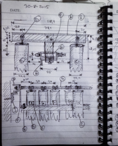
But the tubes were the simplest and easiest part of the instrument. The problem was making a rack that allowed practical placement of the tubes, was easily maintainable despite being placed in the back of a small cabinet, supported a high number of tubes without risking the banging into each other, and of course a system to electrically hit the tubes to make them ring.
This took a lot of thinking and plotting and sketching. Here is part of the original work sketch for the tube rack.
The rack has two rows of tubes separated by a row of linear 12V push/pull solenoids. The “push end” of the solenoid is what hits the top of the tube bell.

The rack is designed as a compact unit, that can be removed and replaced from the cabinet without tools.
At the top, in front of and above the tubes, we’ve placed a piece of transparent acrylic glass (barely visible on the image) with small drilled holes for LEDs – one for each tube – wired in parallel to the solenoid, so we’ll get bright flashes on the pipes as they are playing.
To avoid the tubes hitting each other while played, I placed a tube guard to restrict the movement of the tubes without compromising the sound. The tube guard is just a piece of steel wire inside a silicone rubber tube, as shown in the left image below.
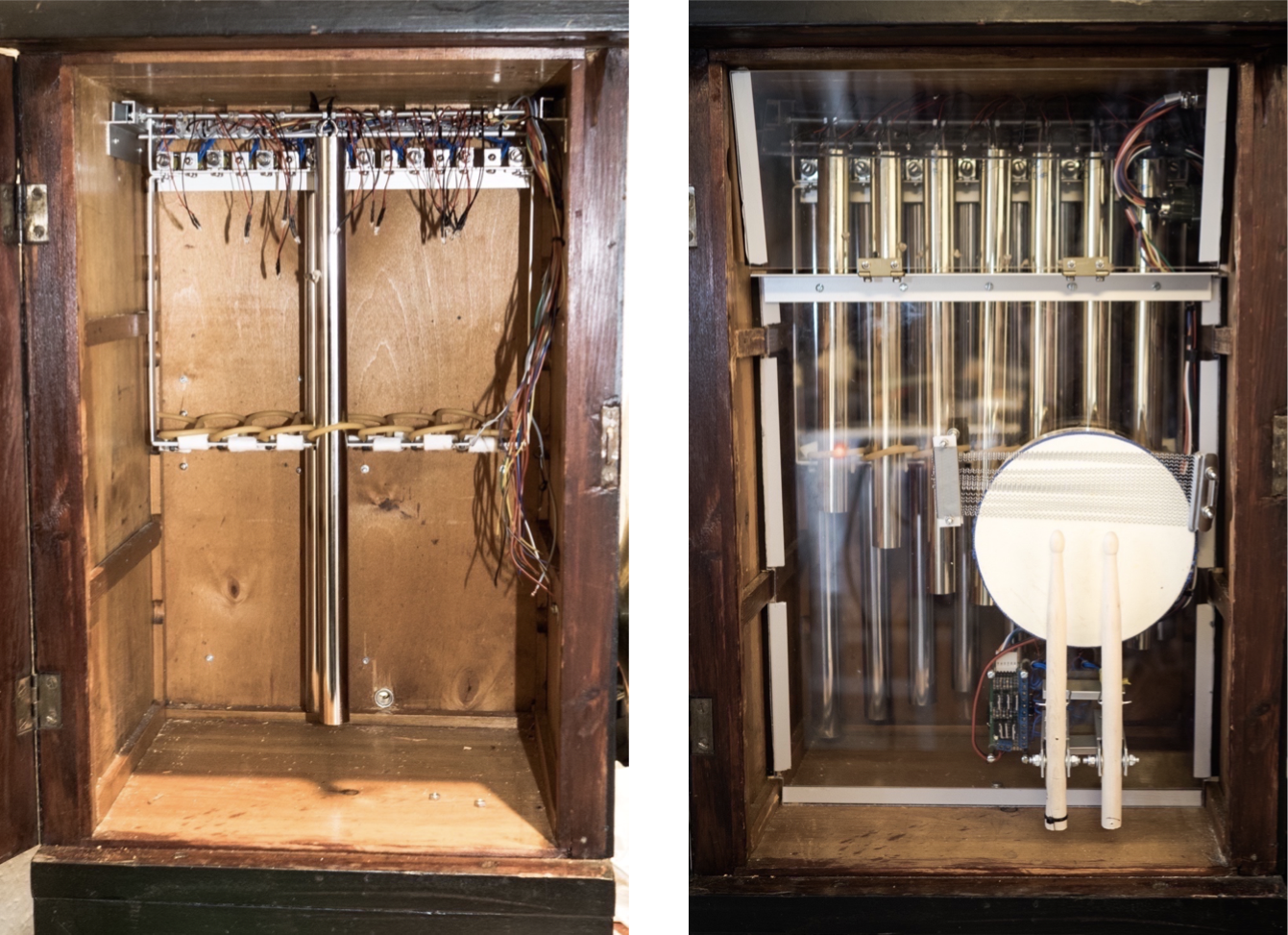
The right image above shows the finished instrument. The wires for the solenoids are connected on the inside to a Y2M aviation connector for easy removal of the tube rack from the cabinet. The wires on the outside of the cabinet are led to the backside, where the driver board is located. To mute the bells a bit places we had to place sheets of acrylic glass in front of them. The bells are very loud, and to achieve some balance with the other instruments, this is a very simple solution. These acrylic sheets also doubles as mounting base for more percussion, like the miniature snare drum.
THE DRIVER BOARD

The solenoids don’t drive themselves. They need lots of current, and to switch that current we use n-channel MOSFETs.
A MOSFET is a kind of transistor that can work as a very efficient electronic switch. The solenoids draw a current of up to about 1A. This is way above anything any logic circuit like a microcontroller can deliver without turning into a puff of black smoke. So, it’s common practice to use some kind of relay or transistor to convert a weak logical (TTL) signal to a large current. MOSFETs are very nice to work with, they only need two resistors to setup, and they work as near perfect switches.
As I was already planning the glockenspiel while building the tubular bells, it was practical to combine the two driver boards onto one prototype PCB, even though the two circuits are not in any way connected.
Below is a partial schematic of a single driver channel from input (i.e. output from the Arduino or, in this case, an I/O expander), through an optocoupler and a schmitt-trigger/inverter, and finally the MOSFET driver and actual solenoid. It’s quite simple, actually, but of course it gets a bit hairy when you need 16 channels.

The tubular bells drivers are activated by the percussion circuitry through a set of I/O expanders.
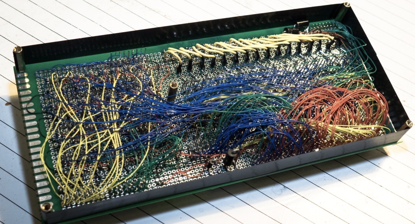
WRAPPING IT UP
Just to wrap up this project, I present the backside of the driver board. Breadboards, stripboards and birds-nests are for amateurs. Oh no, I make my own circuits using the ancient art of wire wrapping. I’ll never understand why it isn’t still the preferred method for prototyping. Seriously. It’s just so easy and durable. And it even looks awesome. Sigh.
And here one of our very first tests of the tubular bells, accompanied by a tambourine placed on the underside of the cabinet (not visible here).
Next: Read about the Glockenspiel
Hello,
Tubular Bells – I’m impressed.
I’m interested in building something similar to your tubular bells.
Can you tell me please.
Which solenoid did you use ?
How did you support the tubes ?
Where on the tube does the solenoid strike ?
Thanks
Chris
Hello Chris
I’m sorry about the long delay!
Designing the tubes, I found a website with lots of information, tables, calculators and more: http://leehite.org/Chimes.htm
The tubes are simply supported by a piece of string. Using the resources on the website mentioned above, I determined the best place to support the tubes, which was at 22,4% of the length from the top.
http://leehite.org/chime_support/04s.jpg
The tubes are all struck close to the top of the tube, at appx. 10-15mm (or 1/2″).
The solenoids are called ZYE1-0530Z 12V/1A. They are Chinese, fairly cheap and easy to mount.
Cheers,
Rune