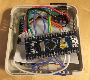
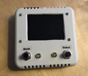
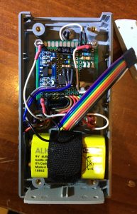
We can’t control all the instruments and parts of the EnsembleBot centrally from a single host computer. That just wouldn’t be practical. Instead we distribute and delegate control to smaller, specialized units, so-called microcontrollers. Many of these are the very common Arduino development kits, but we use other types of microcontrollers as well. Below is a selection of microcontrollers, from the large and user-friendly development kits and more compact versions, to small single-chip micro-controllers:
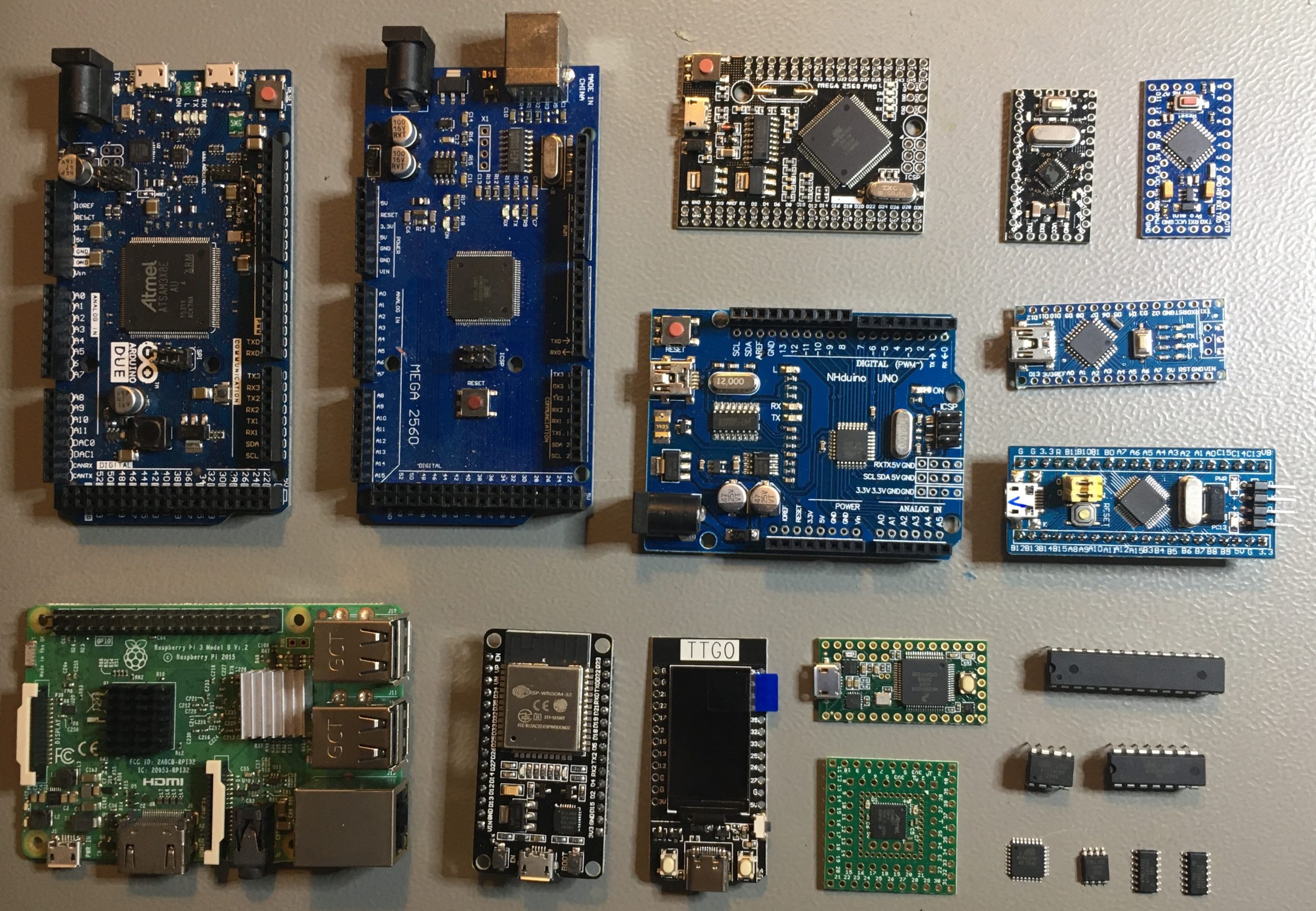
BOTTOM ROWS: Raspberry Pi 3B, ESP32, ESP32 TTGO w. display, Teensy 3.2, SAM15x15, ATmega328P DIP, ATtiny85 DIP, ATtiny84A DIP, ATmega328P-AU TQFP32, ATtiny85-20SU SO8W, ATtiny841-SSU SO14N, ATtiny84A-SSU SO14N
Not all of the above microcontrollers and development kits are used in EnsembleBot, though all of them are or has been candidates for some use in the project. A few microcontrollers not shown on the image should be mentioned as well, especially the classic Maple Mini STM32-based development board and the immensly powerful Teensy 3.5, that we use in the PipeMare controller.
MICROCONTROLLER ENSEMBLE
In EnsembleBot, we want a setup, where the host computer (mac or pc) sends only generalized instructions to the EnsembleBot. And the closer we are to the actual instrument, the more instrument specific the communication and action will be.
We’ve chosen to make our own protocol, called EBP, which is basically a subset of the standard MIDI protocol. So, all commands from the host are in the form of an address (MIDI channel/port), a command (e.g. NOTE_ON or SYSEX) and a value payload (e.g. a MIDI note value and velocity). This protocol describes the communication between the host and the master controller in the EnsembleBot.
The host runs a Max application, basically translating MIDI from a file, sequencer or keyboard into EBP messages, that are sent to master controller via the USB serial bus.
All the Master Controller really does, is queue the incoming EBP messages from the host, and relaying them to the CAN bus for the different attached instruments to pick up.
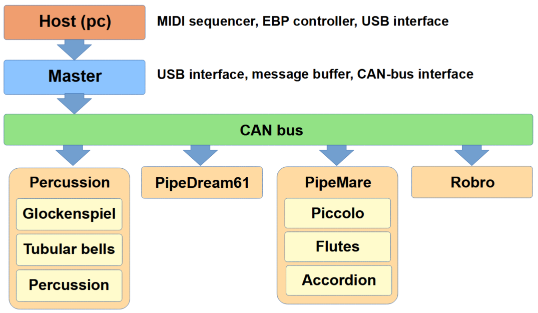
The slave instruments each know how to interpret the EBP commands and how to manage the specific instrument. E.g. neither the host nor the master knows how to play a PipeDream organ or control the its solenoid drivers; only the PipeDream microcontroller knows that. Translating EBP commands into controlling the Robro steel slider or the pick-servos are very specialized actions; only the local Robro slave instrument microcontrollers could possibly know how to perform those tasks.
CHAIN OF COMMAND
So, in terms of communication, the EnsembleBot is a hierarchial network of microcontrollers of increasing specialization. In the following we’ll go through the ever increasing list of microcontrollers currently used in EnsembleBot:
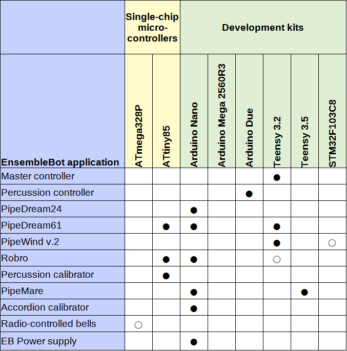
So, we are currently using several different development kits and a few single-chip microcontrollers in different parts of the EnsembleBot. We started out with only the well-known Arduino kits. Now we also use several other similar kits like the powerful Teensy kits, while having more or less abandoned the cheaper STM32 “Blue Pill”. However, we still rely on the Arduino IDE for programming all of the microcontrollers.
The above list also reveals my personal affinity for both the Arduino Nano and the incredible ATtiny85. These have proven both reliable and easy to work with, and most importantly: they are very cheap.
So far, however, we haven’t used any of the very neat ESP32-based microcontrollers. These are fairly cheap and very powerful, but perhaps the most interesting feature is the built-in WiFi. It would probably be too much trouble to use the WiFi instead of CAN bus to tie the instruments together, since timing is both critical and inherently difficult to control in a WLAN setup. But it could let us re-program the instrument controllers wirelessly and give us an easy option to have simple two-way communication with the controllers for tasks like debugging or instrument calibration. Maybe we’ll use an ESP32 in a future instrument, maybe not. While it really is neat, there are also drawbacks, like dependency on a working, known and trusted WLAN, hardcoded WiFi passwords in plain text code, and the risk of having these small, simple IoT devices become a hackers’ gateway into an otherwise secure WLAN.
MASTER CONTROLLER
The master controller is a Teensy 3.2. The Teensy controllers are very much like the Arduinos, but much more powerful. The controller is just a bridge relay between EBP messages, received through the USB serial port, and the CAN bus.
Using a 72 MHz microcontroller like this one is probably overkill, but we really want a controller that is fast enough to avoid congestion and serial buffer overflows. But the Teensy controllers are so easy to work with, and we use them in several other places, so especially the CAN bus libraries are well tested.
MASTER CONTROLLER
The percussion controller used to be an Arduino Mega 2560 R3. This is very much like the popular Arduino Uno, but bigger. It has many more direct I/O ports as well as some more SRAM. It’s a 16MHz processor with 54 digital I/O ports.
Originally, this controller also doubled as master controller. After experiencing some serious problems with buffer overflows, our main concern was that it’s 16 MHz processor was too hard pressed to handle both EBP relaying as well as handling the control and timing of the 15 solenoids in tubular bells, 27 solenoids in glockenspiel and a growing number of percussion instrument solenoids. Fortunately, it was quite easy to replace the Mega with the much more powerful and wonderful Arduino Due. This is a 84 MHz controller with lots of SRAM, built-in CAN bus controller and dual I2C busses.
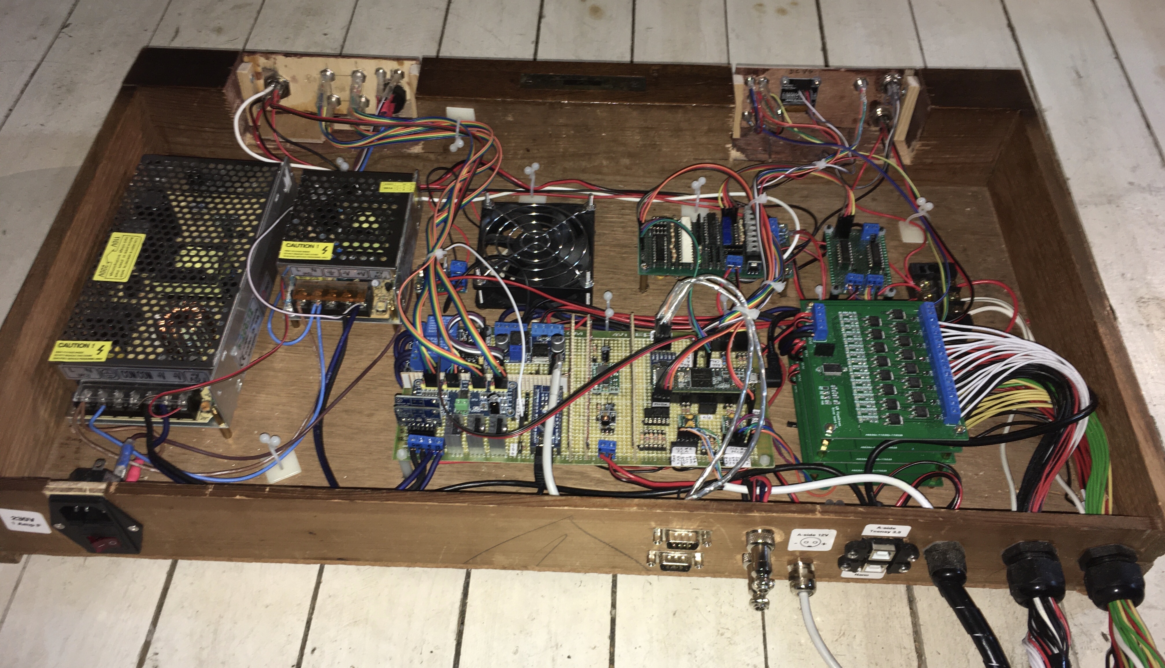
The image to the right shows the backside of the central EnembleBot cabinet. The (old) Arduino Mega is the blue thing in the lower right side. This microcontroller controls the rest of the electronics shown.
PIPEDREAM24 CONTROLLER
The now defunct PipeDream24 was controlled by a single Arduino Nano. The Nano is basically just a compact version of the Arduino Uno, with a 16 MHz processor, 2 KB SRAM, 32 KB flash memory, 22 digital I/O ports and a USB controller for easy programming and debugging. The Nanos are very cheap (< £2) and just as easy to work with as the Uno and Mega.
This microcontroller handled EBP communication via an MCP2515/TJA1050 CAN bus SPI module, translating EBP into the complex activation and timing scheme of the solenoid pipe drivers, as well as a simple monitoring of the controller stack and the ability to turn on/off a cooling fan in the controller box.
The Arduino Nano was just big enough to handle the 24 pipe drivers, but it was evident, that a larger organ would need a larger microcontroller to handle, especially with regards to SRAM.
PIPEDREAM61 CONTROLLERS
As mentioned above, the Arduino Nano was barely powerful enough for a 24-pipe organ, so we needed to think bigger from the start with the PipeDream61 organ with its 61+ pipes. besides controlling the organ, we also wanted control of the auxillary power supply and monitoring the windchest air pressure. We have described many of our considerations for choosing the microcontroller on the PipeDream61 page.
ORGAN CONTROLLER
We actually ended up using several microcontrollers. The main controller, handling CAN bus, EBP parsing and organ control, is a Teensy 3.2. These babies are comparable in physical size to the Arduino Nano, but has a bit more power under the hood. It’s got a 3.3V (5V tolerant I/O) 72 MHz processor, 64 KB SRAM, 256 KB flash, 34 digital I/O ports, all the “usual” bus types (UART, SPI, I2C) as well as built-in CAN-bus controller. We could probably have used a smaller and cheaper microcontroller, but the Teensy is very nice to work with and we wanted to play it safe.
COOLING CONTROLLER
The main organ controller drives a stack of 8 boards with a total of 64 driver channels. The way the drivers dissipate heat into power resistors to reduce overheating in the solenoids means that the driver stack may need cooling from time to time. So, we placed two DC cooling fans in the controller box. These are activated by a MOSFET when the temperature exceeds a certain level, and are controlled by an ATtiny85.
The ATtiny’s are like miniature Arduinos. Though they are just a single chip, they have a built-in processor-clock, SRAM, flash, I/O ports and a number of peripheral busses. The ATtiny85 is one of the smalles in the family, having only 8 pins. Still, it has 512 bytes SRAM, 8 KB flash, a wide voltage operating range (1.8 to 5.5 V), 5 digital I/O ports, a built-in oscillator for up to 8 MHz clock (or up to 20 MHz with external oscillator), and a very low power consumption. Considering that we use 3 of the 8 pins for power, ground and reset, that is quite a lot of functionality. Here we use it to read the temperature from a Dalles D18B20 temperature sensor via OneWire-bus, and turning on/off a pair of cooling fans via a simple MOSFET driver.
WINDCHEST CONTROLLER
But we are not done yet. Inside the windchest we’ve placed another microcontroller to monitor both the PipeDream61 power supply and the air pressure inside the windchest. We need the microcontroller to speak to two INA219 current sensors, a Bosch BMP280 pressure sensor, a 20×4 character display, a PCA9685 module to PWM-control three RGB LEDs, and a dual relay to cut power to the organ in the event of an emergency. That sounds like a lot, but is really quite simple, and so we chose one of the lovely Arduino Nanos.
PIPEWIND MONITOR
To evaluate the quality of our new organ blower setup, the PipeWind v.2, we wanted a good pressure monitor and logger. We don’t just want to check the pressure once in a while (like every second), but we’d like the option to make a series of fast, consecutive measurements to be able to plot a detailed response graph. Our goal is 300 measurements during a period of 3 seconds. Using a BMP280 pressure sensor, the default value type for the measurements is a float, which takes up 4 bytes of memory space. If we were to record 300 measurements, the data alone would use up 1.2 KB. That precludes our default choice, the Arduino Nano, which has only 2 KB, leaving too little memory for the rest of the program. Also, calling a sensor 100 times per second and calculating pressures on the basis of the returned values, does require a bit more processing power than the Arduino standard clock of 16 MHz.
FULL SPEED AHEAD
We are going to have to use one of the faster and more powerful alternatives. In PipeDream61 we used a Teensy 3.2, which would be ideal. It’s fast, small and easy to use. But it’s also quite expensive (~ £20). So, why not try something new?
There are a family of microcontrollers based on the STM32F103C8 chip, called Blue Pills. They look quite a lot like the Arduino Nano, but only on the surface. They operate at 72 MHz and has 20 KB SRAM, 64 KB flash and all the usual I/O ports and peripheral busses. But most importantly, they cost less than £2 a piece.
Admittedly, they are not quite as easy to work with, as the Arduino or Teensy. To begin with, you’ll need to make actual modifications to the board by changing SMD resistors to be able to program it, and then you’ll have to use special hardware programmers and scripts to burn a bootloader onto the microcontroller. Only then can it be used almost like an Arduino. The support libraries for STM32F103 is not complete and does not support hardware I2C. Using a software I2C (like SoftWire) is okay, except that we’ll have to rewrite many of our device libraries to support another base library.
We haven’t actually made it work flawlessly yet, and if it gives us any more trouble, we’ll have to seriously consider using a Teensy 3.2 anyway, although that will be admitting defeat…
UPDATE
Well, so be it. Defeated. The STM32F103C microcontroller turned out to be more trouble, than it’s worth. So, we rebuilt the pressure monitor using Teensy 3.2 after all. Unfortunately, I also decided on upgrading to a larger and faster TFT display, so we had to discard the neat little box in favor of a much bulkier plastic box. No matter.
ROBRO CONTROLLER(S)
The first version of our robot guitar, the Robro, had an Arduino Nano as its instrument controller. Where most of the other slave instruments, like the pipe organs, aren’t as timing critical (they just have to open or close pipe valves within a tolerance of several milliseconds), the Robro is much more demanding.
Besides managing the CAN-bus, EPB parsing, controlling 6 servo motors and 2 rotary solenoids, it also needs to control a stepper motor with a precision measured in microseconds rather than milliseconds. This is too much for a single Nano.
We haven’t decidede quite how we are going to solve the problem, when it’s time to redesign the Robro controller, but we are most likely going to use two microcontrollers, where we dedicate one to the stepper motor alone.
Besides the instrument controllers, we actually have another microcontroller in the Robro. We place the stepper motor driver (a Pololu DRV8834) close to the powerful Nema17 stepper motor in a small grey plastic box. To prevent overheating, we have placed a small 5V DC cooling fan in the box. Just like in the PipeDream61 controller (see above), we solved this with a small ATtiny85 microcontroller, a temperature sensor and a MOSFET driver for the cooling fan.
PERCUSSION CALIBRATOR
Currently, all our percussive instruments are based on linear solenoids, i.e. an electromagnet moving a steel shaft to either hit or pull something to strike a drum, tubular bell, glockenspiel bar etc. The solenoid is activated (or actuated) by sending electrical current through them for a number of milliseconds. But just how many milliseconds differs from instrument to instrument, and indeed from solenoid to solenoid, even within the same instrument. So, for each and every solenoid we need to determine just how many milliseconds actuation we need to obtain a homogenous sound and response.
Furthermore, in several of our the percussive instruments we’d like to be able to express a certain degree of dynamics, i.e. choose through the music if a bell or a drum should sound out loudly or more quietly. And so, the calibration of each solenoid is not just one time value, but a range, going from very quiet (pianissimo, pp) to loudest possible (forte fortissimo, fff).
These values are hardcoded into the master arduino, and setting them by trial-and-error would require an insane number of reprogrammings. To avoid this we made a small handheld solenoid calibrator.
Based on an ATtiny85 and an old LCD display from a Nokia 5110 cellphone, one can connect the output leads to the inputs of the MOSFET driver arrays, bypassing the master. The sends an activation pulse every second, and using the potentiometer on the front we can set a precise pulse length in milliseconds. This enables us to easily test the solenoids one by one, noting the the to extremes (quiet and loud). Then it’s easy afterwards to enter all the values once and for all into the master firmware.
PIPEMARE CONTROLLERS
As discussed in (excruciating) detail in the PipeMare controller page, we had a lot of thoughts about the choice of microcontroller for the PipeMare triple-organ project.
MAIN CONTROLLER
We need the controller to handle a good deal more than the PipeDream controllers:
- CAN bus communication
- EBP parsing
- Timing and handling of two separate ranks of solenoid-based pipe organs
- Timing and handling of a servomotor-based accordion
- In-instrument illumination
- Sweel panel controls
- Monitoring of the dedicated B-side power supplies
Besides the need for sheer processing power and a sizeable number of digital I/O ports, we are going to need several I2C busses to cope with all the devices in the instrument and the accumulative bus capacitance. While there are other ways to solve these problems, we opted for a solution, where the main microcontroller could handle this without the need for too much auxillary circuitry.
And the solution was a Teensy 3.5. This is the big brother of the Teensy 3.2, that we used in the PipeDream61 (see above). It packs a 32-bit 120 Mhz ARM processor with 192 KB SRAM, 512 KB flash, 58 5V-tolerant digital I/O ports, USB controller, 6 serial UARTs, 3 SPI busses, 3 I2C busses, built-in CAN-bus controller and much more. This baby is just what we need. And then some. But it really is a relief not to have to worry about power and capabilities while designing and programming. However, the Teensy 3.5 is quite expensive (~ £25) compared to most of our other microcontrollers, so we’ll have to take extra care not to damage it – we do not have any spares…
POWER SUPPLY MONITOR
We have a dual power supply (5V and 12V) built into PipeMare for the pipes and servo motors, and we’d like to monitor them for current load and temperature control. As the power supplies belong in the B-side power domain (see the master circuitry page for more about the power domains), it would be easiest to set up a dedicated microcontroller on the B-side for this purpose alone.
This secondary microcontroller monitors the operation of the power supplies using two INA219 high-side current sensors. A dual relay can cut the power in case of emergency, and we use a temperature sensor to evaluate if a cooling fan should be turned on. To get some simple (TTL) feedback to the main controller about the state of the power supplies, we’ll use a pair of optocouplers.
There are no particular demands on this secondary microcontroller, so we’ll just use one of the trusty Arduino Nanos.
ACCORDION CALIBRATOR
The PipeMare accordion is a strange beast, based on a large number of cheap, plastic micro-servos pulling open valve pallets. Mechanically the setup is not exactly precise, and each servo will need individual calibration Furthermore, we expect some degree of drift and shift in the valves, so that we’ll need to re-calibrate once in a while, at least for some of the valves. The calibration is essential for the operation of the main controller, so it will have to available to it in some non-volatile way.
As mentioned above, we have made initial calibrations of the percussive instruments’ solenoids using a handheld calibrator, and then burned the calibration values into the master controller firmware. We could do something similar here, having the main PipeMare controller be able to enter some kind of calibration mode, and storing the calibration values in the microcontrollers’ EEPROM. This, however, is very impractical since to calibrate the accordion, you’ll have to stand on a ladder behind the PipeMare cupboard to look into the windchest, and then you can’t see or operate controls on the front of the cupboard. It would be much more practical to have another handheld device to help with the calibration. But we don’t want to re-program the main microcontroller each time we re-calibrate. Hmm.
A NEW GIZMO
Our solution is a handheld device that we plug in between the Accordion windchest and the main controller while calibrating. With simple controls, it should be fairly easy to choose a servo and set values for open and closed positions. The trick is how to make the calibrator store the calibration values so the main controller can read them later. The calibrator can’t write it back to the main controller. So, the only option is to place an EEPROM I2C module inside the accordion windchest. The calibrator can read and update the EEPROM values during calibration; and the main controller can read them during power-on initialization. It’s a strange solution, but it should work.
Anyway, again there are no special demands regarding choice of microcontroller, and the devices inside the accordion windchest works just as well at 3.3V as 5V. So, once again, we’ll probably end up using an Arduino Nano.
RADIO-CONTROLLED BELLS
Though not yet built, we’ve done some preliminary designs and tests of our radio-controlled, battery-driven, tuned bells. There are still a lot of undecided design options, like what radio devices to use, but we are pretty much decided on using the ATmega328P as microcontroller in each of the small receiver units.
The ATmega328P is the microcontroller chip we use in the Arduino Uno, Nano and Pro Mini development kits. In principle, the ATmega chips can be used without any supporting circuitry, just like the ATtiny’s mentioned earlier. To save space inside the receiver units, we are going to make a PCB for the circuitry, and use the small SMD version of the chip.
Next: Read about the Tubular bells


