Personally, I’ve always wanted to build an organ with reed pipes, like an oboe rank, or clarinet or trumpet, but those are a bit harder to come by. But we can still get some reeds by butchering a harmonica or accordion. The sound is not the same, of course, but it would be a welcome change of timbre from the more conventional organ pipes.
Instrument status: Finished, but needs final testing and calibration
DECONSTRUCTED ACCORDION

We’ve got our hands on an old, battered accordion. Instead of keeping it intact and think up some way of working the bellows and pushing the buttons, we tore it completely apart.
The bellows will be repurposed as part of the reservoir and pressure regulator in the PipeWind v.2 project, as it was too nice a component to throw away.
The melody reed banks has a range from G3 (196 Hz) to E6 (1319 Hz), while the bass bank spans from F2 (87 Hz) to E3 (165 Hz). That means that we actually don’t have a complete chromatic range, as F3-F#3 are missing between the two banks.
The right-hand keys, the housing and the intricate left-hand bass key system are of no practical use to us, and so we discarded them.

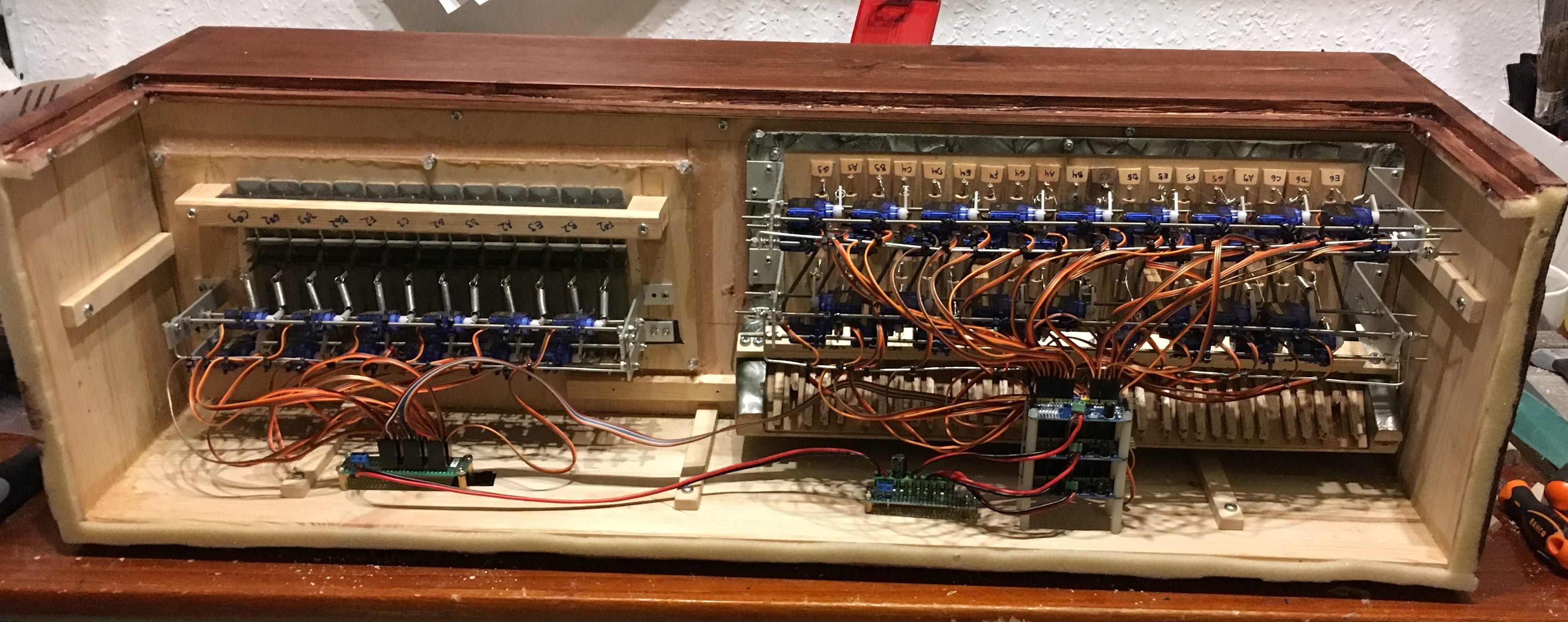
What we kept were the actual reed ranks that make the sounds, as well as the valve boards for the reed ranks. These will be made into a new, electromechanical instrument.
Much like the pipe organs, the sound-giving parts (the reeds) are placed on the outside, and fed air from a windchest though internal valves.

Instead of the accordion bellows providing air for the reeds, we build an organ-like windchest which will be under constant pressure. So, we take the two valve boards and place the side-by-side on what will become the front of the windchest.
The valve boards are of course purely mechanical. So, we need to find a way to activate them electrically in a satisfactory manner, i.e. in a way that is fairly easy to build, reacts fast enough, is reliable and easily controlled, and, importantly, relatively cheap.
RECONSTRUCTED ACCORDION


Given the actual physical characteristics of the valve boards, they are not exactly suited to the linear solenoids that we usually resort to when something needs to be pulled or pushed.
Inspired by the Robro project, where we use micro servos to pick the strings, we are attempting to use that same kind of servo motors for these valves. They are fairly cheap, fairly easy to mount and can be electronically calibrated.


However, they do lack something in speed compared to solenoids. The solenoids completes a full actuation in about 20 milliseconds, enabling a solenoid valve to easily play very fast and staccato. The small and analog micro servos are much slower than that, and they might end up having problem playing fast notes. The micro servos may also lack some stability, and we haven’t much experience with long term use.
Here is a demonstration of the servo action without wind pressure:
SERVO DRIVERS

Perhaps the easiest way to control several servo motors is to use a dedicated PWM driver. There is a cheap and well-known breakout board out there based on the PCA9685 16-channel I²C PWM driver chip, complete with power screw terminals, 3-pin servo headers and a nice design for daisy-chaining or stacking multiple boards. Awesome. These will do very nicely.
To keep the I²C bus length down, we could place the PWM boards close to the master and the pipe driver boards. Then we would have to find a way to lead the 46 PWM signals from the driver boards, into the harmonica windchest and into the servo motors.
However, this is just too much trouble. It’s bad enough that we’ll have to draw 75 control lines to the two pipe organs.
No, it’s much easier to place the PWM drivers inside the harmonica windchest close to the servos, and there is plenty of room. We made performed some tests, and we can reliably run the bus at 400 KHz (I²C high-speed mode), even with a 1 meter bus cable. Using a CAT5e cable, appropriate pull-ups, and sensible use of the twisted cable pairs, there seems to be no problem at all.
SWELL
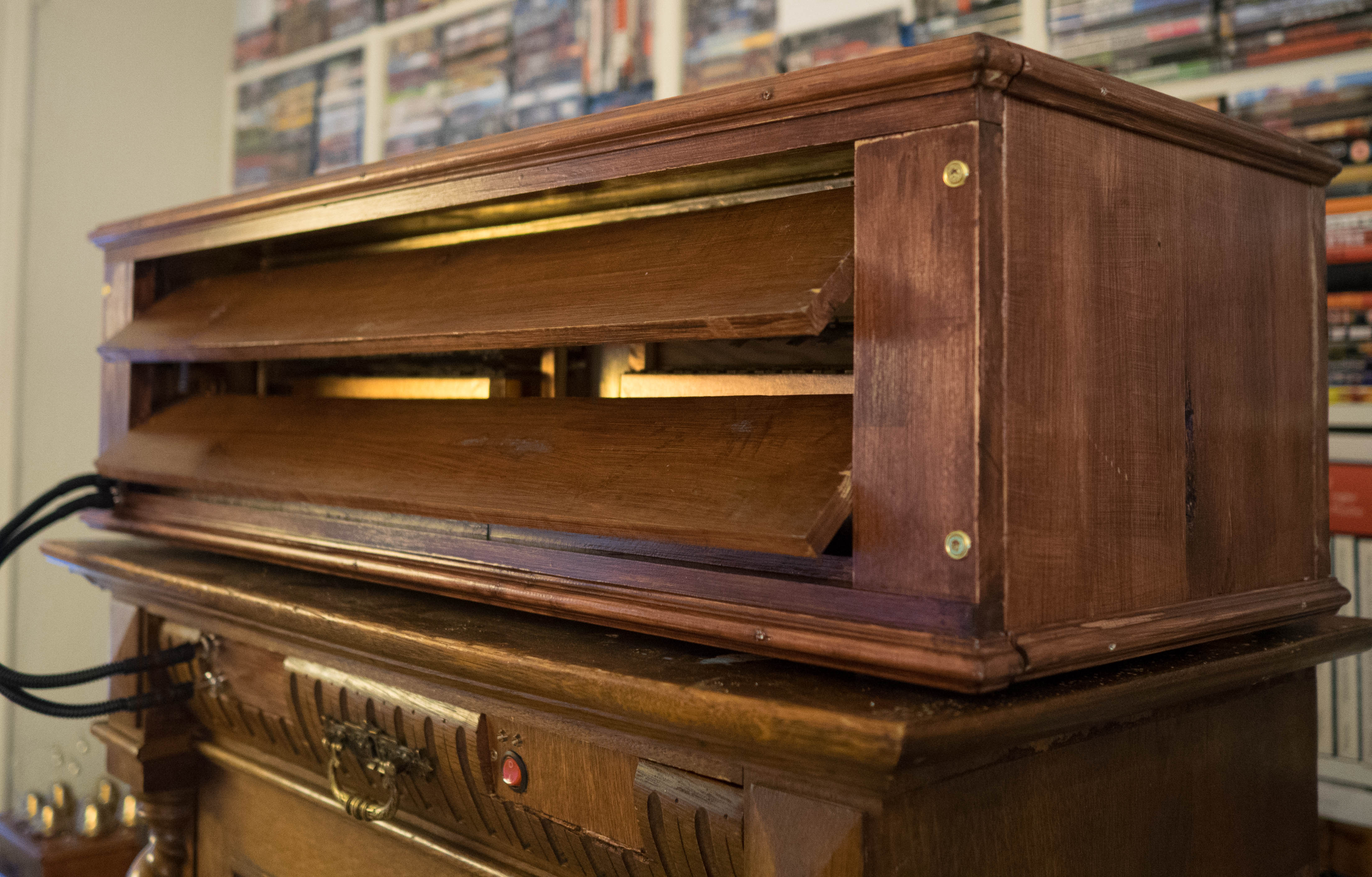
The insides of the front part, i.e. the reed banks on the outside of the valve boards and their surrounding enclosure, are painted gold or pimped with golden adhesive tape. This is to enhance the illumination effects of the orange LEDs mounted in the front panel and swell.

The swell (below) is operated by a small and silent geared DC motor. The two swell panels are mounted on small ball bearings and are coupled for synchronous action. Two microswitches are placed to mark the open and closed position.

ELECTRONICS
The electronics are based on the very common PCA9685 based 16-channel PWM driver boards that are perfect for driving servo motors. They are controlled via I²C bus (see more about that in the PipeMare controller page). Besides the driver boards, we also place an I²C EEPROM module (AT24C256) in there. Why? Well, that’s a long story.
The very mechanical accordion valves and servo motors will need a lot of very precise and individual calibration, where the PipeMare controller needs to know the exact PWM values for both the open and closed position of every single valve servo. We could hardcode these values into the controller firmware, which would require a full re-programming each time we change a value. That is not practical. It would be much better to store the values in EEPROM (the on-board rewritable but persistent memory on most microcontrollers), and then program some sort of calibration mode into the controller firmware. But there is a very practical problem.

To facilitate calibration without disassembling the windchest every time, we made the top of the pressurized part of the windchest transparent. Combined with built-in white LEDs in the windchest, it should be possible to calibrate the valve servos both visually and aurally. But you have to stand on a chair behind the windchest to see anything at all, and the PipeMare controller at on the front of the cabinet.
So, our solution is to make a small portable calibrator device we can plug into the accordion windchest instead of the controller. This calibrator will have a small display and some knobs and buttons to cycle through the servos and determining the appropriate values for the open and closed positions.
But such a device can’t access the PipeMare controller EEPROM. So, instead we place a dedicated EEPROM inside the windchest, which then will be accessible by both the calibrator and the afterwards the PipeMare controller.
STATUS
[June 2018]
The accordion is practically finished and has undergone initial and succesful pressure tests. We still need to make the calibrator, and then, of course, we need pretty much all of the rest of PipeMare, before we can really test it.
Next: Read about the PipeMare Piccolo
