Instrument status: Finished, but defunct. This organ project has been surpassed and replaced by the larger and better PipeDream61 organ. However, the PipeDream24 test organ project gave us a lot of valuable experience. The article below describes the project, design choices, successes and mistakes. Many of the lessons learned formed the basis of the larger PipeDream61 organ.
THE TEST ORGAN
The EnsembleBot is not just about hitting stuff. We also wanted a pipe organ. Building a pipe organ, however, is quite challenging and a lot of tests and experiments were needed, before we could commit to building a larger organ. So, to begin with we built a 24-pipe test organ, pieced together from scrap, cheap materials and miscellaneous non-matching pipes.
Here is a small demo of our bastard test organ:
Yes, we know. Absolute perfection, right? Right? Well, okay, it sound horrible, but as a proof of concept it’s a great success. But let’s step back and start at the beginning, and then we’ll get back to why it sounds as it does, later.
PIPE ORGANS FOR DUMMIES
A real pipe organ, like the great organs of churches and cathedrals, are fantastically complex machines based on know-how and techniques accumulated over many centuries. Because we are dummies, we’ll try to make it much simpler, cheaper and based on only a few random google searches.
But no matter how simple we make it, there are still some fundamental parts of any pipe organ that must be considered:
- A blower to produce the wind to make sound in the pipes. The blowers in modern organs are powerful electrical motor blowers.
- A pressure regulator to ensure a constant air pressure to the organ. The pressure regulator is usually a combination of some kind of bellows and an air reservoir. This is a very important component. Organ pipes are very sensitive to pressure changes, because they result in noticeable pitch shifts. The pressure must be held constant and compensated, and without a pressure regulator the pressure would change depending on which and how many pipes are playing at any given moment. The regulator is placed between the blower and the organ windchests.
- A windchest under pressure with valves for letting out air into the pipes. The windchest itself is basically just an airtight box with a large air inlet from the blower/regulator, and a number of valves.
- The valves are normally closed, keeping the air inside the windchest. But on command (either mechanically, pneumatically or electrically) a valve can open to let out air from the pressurized windchest and into a pipe. In a typical organ the valve opens as the player presses a key on the manual to play a note. Our “player”, however, is the EnsembleBot.
- A toeboard and a pipe rack for mounting and securing the pipes. The toebard is in our case just the top side of the windchest. It’s called a toeboard because the bottom part of an organ pipe, where the air is blown in, is called the toe. The toeboard has holes prepared for the toe of each pipe, and to keep the pipes securely upright they are supported by a pipe rack. This is simply a raised board with holes for the pipe feet (the lower conical bit of the pipes).
- And, of course, the organ pipes themselves. There are many types and sizes of organ pipes, but we have chosen our pipes solely on availability, price and size.
Now, of course, a real church organ has many more essential components, and each of them infinitely more complex and intricate, than we are able to design or make them. And, of course, a real organ has manuals enabling a human to play the organ. But we try to keep it simple, and like in space travel, the best way to simplify things is to remove the human component altogether. Instead, we have an organ controller and driver connected to the EnsembleBot master circuitry via CAN bus.
In the following we’ll go through the construction of PipeDream24 and the choices, compromises and mistakes we made. However, designing and building the blower/regulator is described seperately under the PipeWind v.1 section.
WINDCHEST
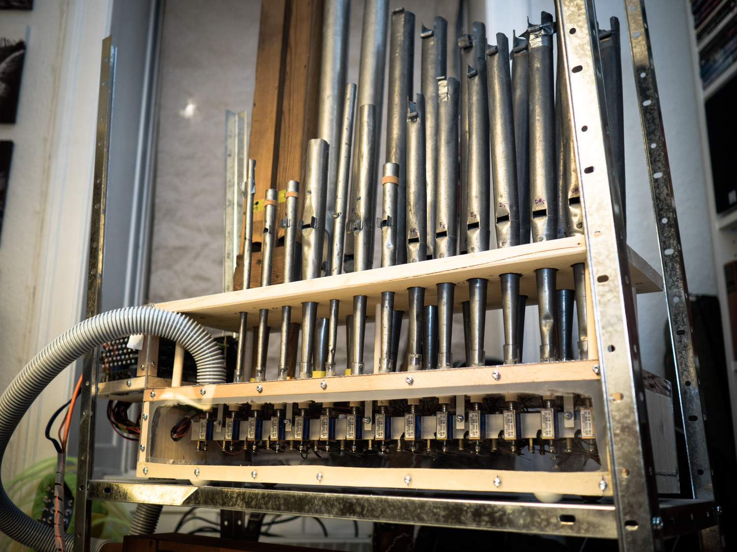
The windchest is built of very cheap materials indeed, mainly 18 mm pine boards the front is made of transparent acrylic glass, as much for effect as to be able to see what’s going on inside the windchest for easier “debugging”. The chest has a connector for ∅ 32 mm flex-tube from the pressure regulator, and three 9-pin aviation connectors for controlling the 24 solenoid valves inside. Being a test organ only, we do nothing to make the organ look good.
But frankly, the windchest itself is not particularly interesting. It’s more or less an air-tight box, and could have been constructed in a hundred different ways. No, the interesting stuff is the pipe valves.
VALVES
How do we activate an air-flow from the pressurized windchest into a specific pipe? There are tons of different principles for both the valves as well as their activation – or action – in both historical and modern organs. But basically they can be grouped into three major principles:
- Mechanical action
- Pneumatic action
- Electro-mechanical action
… and of course all manner of combinations.
The mechanical action relies on the valves being opened by pressing a key on the organ manual, often through complicated mechanical connections of rods, strings and/or levers. So, it’s actually the force from the players’ fingers that activate the valves. That is no good in an organ, where we removed the human component.
So, we look at pneumatic action. This is where the valve is opened using some kind of secondary pneumatic system, either inside or apart from the windchest, but typically utilizing the pressure differential between the windchest and the atmospheric pressure. There are a million ways to do this, and one of the most established principles is using so-called chest magnets combined with secondary pneumatic motors, like in classic Wurlitzer organs. This indirect action, however, is a rather complicated affair, and not something to try in your first pipe organ. So, that’s out, then.
Another option was to use direct primary pneumatic action, using an array of electro-pneumatic valves. But although these do exist and are used for a variety of pneumatic applications, they are insanely expensive and not as fun as building a “real” organ.
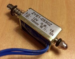
That leaves us with direct electro-mechanical action. The most common way of using direct action is to use electromagnetic organ valves as the ones shown here. It’s an electromagnet that when powered pulls the levered arm towards the steel protruding from the magnet. A valve pallet (normally covering the air exhaust hole to the pipe) is mounted on the arm, and so directly opens up for an airflow (hence the term direct action). Unfortunately, such magnets are specialist organ components, and therefore rather expensive, unless you stumble upon a batch of used valves (which we did, incidentally, albeit too late for both the PipeDream24 and the later PipeDream61).
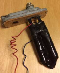
Another option is using micro-servos like the one shown here. They are relatively cheap and could provide a more interesting dynamic actuation instead of purely on/off action. However, these babies are somewhat unreliable and erratic, and they need a lot of calibration, but most importantly, they are too slow.
Well, what then? From building the tubular bells and glockenspiel we gained some experience with linear solenoids. They are relatively cheap when purchased in bulk from China, and they are easy to work with, both mechanically and electrically. Then why aren’t they used regularly in pipe organs?
Well, there are three main reasons:
- Reliability: The moving part is a steel shaft moving inside an electromagnet casing, and friction alone reduces the life expectancy of the device. Remember, most pipe organs are built to last decades if not centuries.
- Noise: We will get back to this in a moment, but the mechanical noise of linear solenoids are rather offensive.
- Current and heat: It takes a lot of electrical current to actuate these solenoids, and high currents make the solenoids overheat in seconds, making it more problematic to design a solenoid driver that solves both problems. More about that later.
Suffice it to say, that since we’re not building for future generations, and since a bit of mechanical noise in the EnsembleBot will just enhance the charm, we decided on using the linear solenoids.
DESIGNING THE VALVES
To test if it was even possible to make an organ valve using direct action linear solenoids, we created a miniature windchest with two valves and pipe holes.
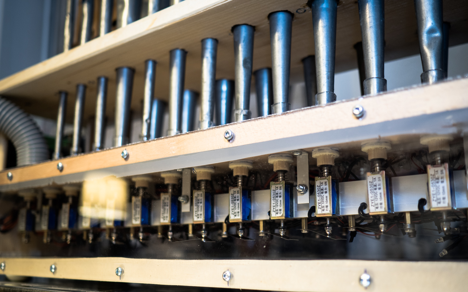
The valve pallets are made of a thin piece of soft leather silicone-glued to a felt pad, mounted on a piece of wood that fits the solenoid shaft. Very simple and easy to make.
The first test was actually a great success, and the valves performed well, although a bit noisy. Anyway, we then rushed on to build the actual windchest and valve ranks. To ensure a good seal when the valve is not activated we placed a piece of blade steel spring on the opposite end of the shaft on each of the solenoids, individually adjusted for a uniform performance.
But as mentioned above, there is a pronounced noise problem when using linear solenoids, as this demonstration without air shows:
The linear solenoid shafts are basically pistons moving violently between two extreme positions, and no matter what you do, it’s going to make some noise. But adding to the noise of the solenoid itself is the noise of the pallet closing, producing a loud pop! after each note. This is something we’ll have to think about when we design the next organ.
PIPES
O Danny Boy, the pipes, the pipes are calling! This being a test organ and really a test of whether it’s even possible to make a cheap, homemade pipe organ, we didn’t want to spend too much on pipes at this stage. So, we found some old cheap pipes here and there, until we had about 30 pipes of odd types and different states of disrepair.
We selected 24 pipes to use:
- 3 wooden gedackt diapason
- 16 lead/tin diapason from different ranks/organs
- 3 quintade/gedackt
- 2 viole
The pipes are not in a single continuous tonal range, the lowest being G2 (98 Hz) and the highest F6 (1397 Hz), but fortunately we do have an unbroken chromatic series of more than a full octave from G4 to C6. The pipes vary in both timbre and pressure response, making it very hard (impossible) to calibrate and tune the organ to a homogenous sound, which the sound demo above demonstrates.
HOW TO DRIVE A SOLENOID CRAZY
Using cheap Chinese 12V solenoids poses another problem besides noise: power dissipation. These are so-called intermittent solenoids. They are made for short actuations, drawing about 800 mA for perhaps a fraction of a second before it’s released, just like we used them in the tubular bells and the glockenspiel.
However, that’s not how an organ plays. An organ needs to actuate a pipe valve and hold it for a shorter or longer period determined by the music. If we just let the solenoid have its way with current, the internal heat build-up would destroy the solenoid in mere seconds, because the tightly wound copper wires just can’t get rid of the heat fast enough. Incidentally, “normal” organ valves like chest magnets or pallet valves do not suffer from this problem, as they require much less current to acutate (and therefore don’t build up critical heat) and are wound with thicker or longer wire to better cope with heat dissipation. But for our solenoids this is a serious problem, and something that needs to be solved.
The graph to the right shows the temperature rise in the solenoid core over time at different power levels. At 12V we’ll have a power level of 9.6 W, i.e. somewhere between the 7.2W and the 18W curves in the graph. As holding a note for several seconds, if not tens of seconds, is quite normal in organ music, we’ll soon hit a citical temperature.
Basically, we need a solution that supplies full current to actuate the solenoid, and then – after a few milliseconds – switches to a lower current that is just strong enough to hold the solenoid open, while at the same time not generating too much heat in the solenoid coils. There are (as always) several solutions to this problem, but especially two models are worth looking at.
The first solution uses PWM (pulse-width modulation) to control a current limiting circuit, and the other uses two parallel current drivers, where one is attenuated with a current limiting passive resistance. Both solutions demand a more complex driver circuitry, than we used for the tubular bells. Where the first solution (PWM) is the most energy efficient and elegant, the second solution (dual channel) is the easiest to build. And we always take the easy way out.
DESIGNING A SOLENOID DRIVER
We need a circuit that combines a short actuation current (appx. 30 milliseconds) with a lower holding current of indefinite length. The holding current must be high enough to keep the solenoid locked in position, but low enough that the heat build-up as a result of power dissipation is low enough for the solenoids to be able to get rid of the heat. This is illustrated here:
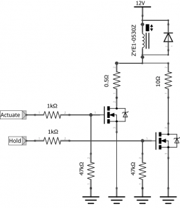
This can be done using a MOSFET driver circuit like the one below. For each solenoid we need two I/O signals (TTL) from a controller, one for the short actuation and one for holding the pipe for the duration of the musical note.
Note that the only difference between the two MOSFET drivers is the value of the serial resistors. The actuation channel has only a very small/neglible resistor (0.5 Ω), whose primary function is reducing electrical noise. The holding channel has a larger power resistor. The schematic says 10 Ω, but we settled on 12 Ω / 10 Watt, closer to the real impedance of the solenoids (appx. 15 Ω). This almost halves the current flow through the solenoid in its holding phase from 800 mA to 444 mA, greatly reducing the power dissipation from 9.6 W to 3 W, and so slowing down the heat build-up. As seen in the graph above, this makes a lot of difference.
However, we still burn away a lot of energy, but now we move half of the heat build-up to the series resistor. On paper this is very energy inefficient, and we are buning away 3W in the power resistor while holding a note. We need resistors that can deal with that, and to be safe we chose 10W power resistors.
In principle we could control the two MOSFETs with just one I/O port. The I/O port would control the holding channel, while the actuation channel is slaved to an R/C (resistor-capacitor) coupling activated through another transistor activated by the I/O signal, and perhaps a schmitt-trigger to ensure a clean TTL signal. But to be able to calibrate each driver to the precise actuation time needed, we’d need to make the R/C resistor a potentiometer, and then we are beginning to have a larger and definately more expensive circuitry. And since simple I/O ports are easier to make, we again went for the easier solution.
DRIVER BOARD
Though inefficient and bulky and taking up a lot of I/O ports, this solution proved very reliable. Now, we just need to make it into a driver for 24 pipes. We knew that if the PipeDream24 were a successful test, we would move on to design a bigger and better organ based on the same principles. With that in mind we decided to aim for a modular and scalable pipe organ driver design.
This organ has 24 pipes, which means 2 × 24 = 48 MOSFET driver channels to control. The PipeDream61 organ (that we were actually planning while designing and building the PipeDream24 test organ) has 61 pipes, thus needing 2 × 61 = 122 MOSFET channels, and just as many I/O ports. That’s a lot, and definately more I/O ports than any Arduino.
In our EnsembleBot master circuitry we use MCP23017 I/O port expanders to create more I/O ports using the the I²C bus. Each of these I/O expanders (from now on called IOX) offers 16 I/O ports, and they are 3-bit addressable, meaning we can have up to 8 IOXs on the same bus. This gives us a maximum of 8 × 16 = 128 ports, which fortunately is just enough for even the bigger PipeDream61 organ. So, now we have a working driver stage and a well-known IOX-technology. All we need is a practical design.
To ensure shortest bus wiring and room for the rather large power resistors, we ended up with a PCB design using a full standard 160 × 100 mm board with ports for one IOX, i.e. 16 I/O ports or 8 pipe driver channels.
Since we need uite a few of these driver boards (3 for PipeDream24 and 8 for PipeDream61) it was cheaper (and much, much easier) to have the PCBs etched, drilled and silk-screened in China. The components are pretty standard, though a mix of THT (thru-hole) and SMT (surface mounted) components.
In the image above we have the MCP23017 IOX to the far left. Just above it is a 4-pin stackable connector for I²C to other boards, and below is 3 solder-jumpers to set the I²C address of the current board IOX. The white rectangular things are the 12 Ω power resistors. Below is the row of 16 logic-level N-channel MOSFETs (IRLR2905), and for each MOSFET there are the two gate resistors, an LED indicator and a series resistor for the LED. SMT components are just awesome.
Using the 4-pin connector for the I²C-bus, the boards are easily stackable:
The video below demonstrates actuation of the 3 × 8 driver channels. The dual channels are visible as a red light (the short actuation) and a blue light (the longer holding current). The fast part of the test sequence also demonstrates, that there is no problem with delay/latency.
INSTRUMENT/SLAVE CONTROLLER
On top of the driver stack we put the organ controller circuitry. The PipeDream24 works as a slave instrument to the EnsembleBot master, and so it needs its own microcontroller to parse MIDI/EBP messages from the master/host and manage the organ drivers. We chose an Arduino Nano as the “brains”. See our microcontroller page for more on this.
As discussed elsewhere, we are using two separate power domains – the A-side for microcontrollers and communication, and the B-side for all the inductive components like solenoids and motors. The organ controller receives CAN bus messages in the A-side power domain, and this is where the Arduino Nano also resides. The pipe driver boards, however, belong to the B-side.
So, not only must the organ be supplied with both A-side and B-side power, but we must find a way to have the I²C master (the Nano) in one power domain, and all the I²C slave devices (the IOX driver boards) in another galvanically isolated domain. In the master cicuitry we used optocouplers to isolate simple TTL signals. We could in theory have done the same here, keeping the IOXs in the A-side domain and then optocoupled each output port to the B-side. But that would mean setting up many optocouplers as well as support components. No, it would be easier to somehow make the I²C bus bridge the power domain gap without compromising the isolation.
Fortunately, this is extremely easy using an I²C isolator chip like the Texas ISO1540. This little 8-legged marvel offers transparent capacitive isolation of the I²C bus without any problems, and it works effortlessly at bus speeds in excess of the standard 400 kHz.
With that settled, it’s just a matter of piecing the things together:
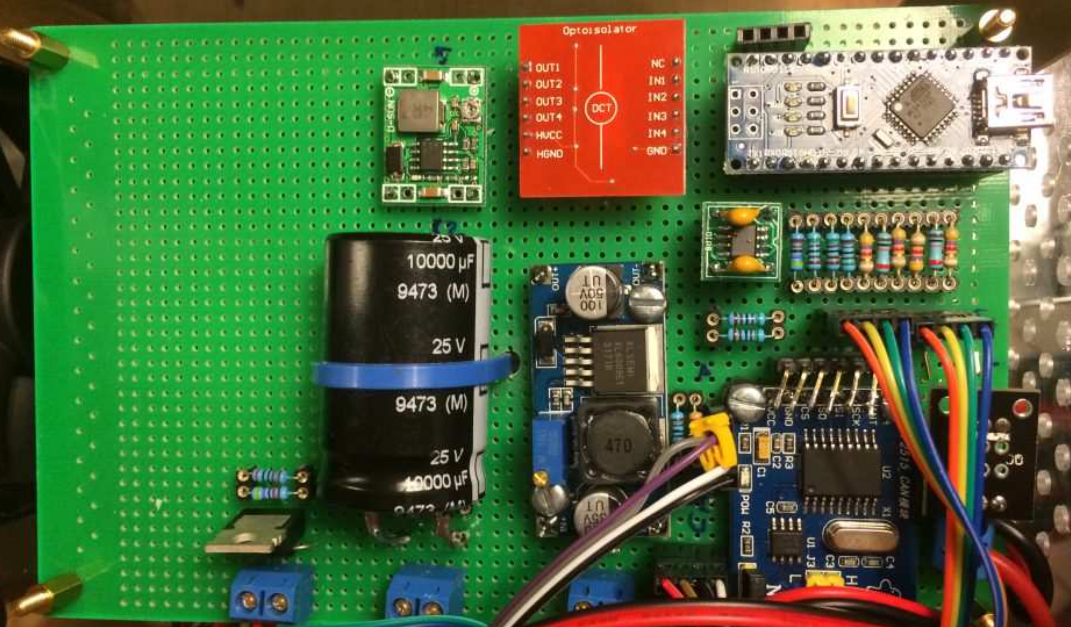
Besides the Nano, CAN bus module and ISO1540 I²C isolator, we also have a few DC-DC converters, a large reservoir capacitor for the B-side, a Dallas DS18B20 temperature sensor and a MOSFET driver for a cooling fan. The red square is an (upside-down) optocoupler module with 4 channels, though we ended up only using one channel to isolate the MOSFET fan driver from the A-side.
The controller and driver stack enclosure is mounted at one end of the windchest, and provides connectors for both CAN bus and power.
There is also a switch and a potentiometer used for pipe calibration. When throwing the switch, the controller enters calibration mode where it turns on a single pipe depending on the position of the potentiometer. By turning the potentiometer one can easily cycle through all the pipes in turn without having to connect a MIDI keyboard to the host and pressing a key while tuning the pipe.
SLAVE FIRMWARE
The instrument Arduino firmware is nothing special. It basically listens for CAN messages addressed to itself, translates NOTE_ON and NOTE_OFF events to pipe activation/deactivations, while all the time keeping track of the pipe drivers. Using a simple algorithm it accumulates a heat index for each pipe driver as the pipe is used. If a pipe has been active (playing) for too long without sufficient cooldown, the pipe stops responding until a certain amount of time has passed to ensure cooling.
Allowing for an (admittedly arbitrarily chosen) allowed maximum core temperature rise of 30 °C, we can have a continuous actuation/holding time of at least 40 seconds at 3W power. The valve timer counts the seconds 1:1 while the solenoid is activated, but when the driver turns off the solenoid, this accumulator decreases 1:2, because it takes longer to shed the heat, than to build it up. So, if the solenoid has been active for 5 seconds, it will take 10 seconds for the accumulator to reach zero. In some musical pieces, where the same note is used extensively (e.g. a continuous drone), there is a risk of the accumulator for a valve reaching the 40 second mark.
SUMMARY
Well, that was a lot of text. Sorry about that. Anyway, while PipeDream24 had some very obvious problems (noisy valves, leaky windchest, energy inefficient drivers, ugly design, horrible pipes etc.), it was still a great success, performing above and beyond our expectations. It proved the concept and taught us enough to design and build the new, bigger and better PipeDream61 organ.
But let’s end with one of the only recorded “performances” of the PipeDream24, accompanied by both tubular bells, glockenspiel and percussion. Here is the Cantina Band theme by John Williams (audio only):
Next: Read about the “real” organ, PipeDream61











I’m building an electronically controlled busker organ with organ pipes and I chose to use servos, those very same you pictured (TowerPro). They are a bit slow, but since I won’t play the instrument from a keyboard, the slowness doesn’t matter, as long as the attack of each sounding tone is fast enough. And it is, according to a test I did with a smaller windchest and a single pipe. The final product has 32 pipes.
Cool! I actually use 46 of these servos in our accordion. They are indeed slower than solenoids, which in our case may cause problems. But my main concern is actually the longevity of these servos, as they are more complex, both mechanically and electronically. Time will tell.
This is truly amazing! I’m building a 4 rank pipe organ that also uses those 12vdc micro solenoids. There will be at least 124 pipes with their own solenoid. And I had a similar problem with heat build up. For a while I had made my own solenoids but they weren’t as efficient and cheap as the (made in China) 12vdc 300ma solenoids. My homemade solenoids would heat up twice as fast as the factory made solenoids. With that said I plan to use the factory made solenoids for the whole project along with using a higher amp rated transformer and using a PWM controller to hopefully solve the heat build up. Is there anything else I should consider, such as voltage drop?
Hello Steve.
I have thought about this quite a bit. There are some problems using PWM with MOSFET drivers and solenoids. The solenoids are essentially electromagnets, and they work by building up an electromagnetic field when the power is turned on, and when the power is turned off, this field has to dissipate by inducing a reverse current. This doesn’t happen instantaneously, but takes maybe a few hundred microseconds. Normally, this is not a problem, but when you drive the solenoid with PMW from a microcontroller, you essentially turn them on and off at a frequency of 500-2000 Hz. This is slow enough that the field has time to build up and dissipate completely with each cycle, meaning that the heat build-up in the solenoid is potentially worse, than with DC current.
The solution is to use a faster PWM, like a PCA9635 PWM driver with a 97 kHz PWM frequency. This is fast enough, that the electromagnetic field doesn’t fully dissipate between cycles. However, to drive MOSFETs that fast, you’d need a to use some special MOSFET drivers to overcome the bus capacitance between the microcontroller or PCA9635 and the MOSFET. Otherwise, the MOSFET will spend too much time between fully open and fully closed, which leads to overheating in the MOSFET. I learned this the hard way, after having a stack of PCA9635 driver boards printed without using a MOSFET driver.
I made that mistake, so you don’t have to 🙂
Happy New Year!
Thank you so much! Although I’m not that familiar with micro controllers and MOSFETs wiring, I’m familiar with normal bus bar wiring, connected to each solenoid being the positive and then the other end of the solenoids are connected to a ground via switch. I know this sounds way more simplified than how it works. So my question is can you just power the bus bars with a high frequency 12vdc instead of powering each solenoid independently with their own MOSFET?
Thank you so much!
Happy New Year!
Sorry about the late reply. Well, hmmm. The problem about oscillating the common bus bar is, that ideally you want to control the PWM duty cycle individually for each solenoid. Upon activation of a solenoid, you want a 100 % duty cycle for the required number of milliseconds to fully actuate the solenoid at full force. Only then can you switch down to a lower duty cycle, e.g. 20 % on, 80 % off, or whatever is enough to just hold the solenoid actuated. I suppose it’s possible to switch the entire bus, but I don’t know if it’s practical. I actually never thought about it. If you can pull it off, it could simplify the driver circuitry quite a bit. Interesting.
Great project and write up!
Have you also worked with Sandra Boss in the past? This project looks quite similar to the organ used for her LUFT piece: http://sandraboss.dk/projects/organ-works-2/luft/
It does indeed look similar, but then again, a basic organ windchest and a bare pipe rack would look similar, I guess. But no, I was not aware of the work of Sandra Boss, until now. Thanks.