
While building our small organs, we needed a steady air supply. There are three major requirements of an organ blower: air flow, constant air pressure and low noise. This means designing and building small organ blowers with reservoir, pressure regulator and so on.
For our first organs, the PipeDream24 and PipeDream61, we built a small blower called PipeWind v.1. As the EnsembleBot grew, the need for air grew accordingly, and based on our experience with v.1, we built the PipeWind v.2 organ blower. See those pages for more specific information on these blowers.
Below we’ll go through some of the basics in providing air to organs, dumbed down to our level.
ORGAN BLOWING 101
There are three major requirements of a so-called organ blower:
- Sufficient air flow to make a sound
- Constant air pressure to obtain a suitable volume and a stable tone
- Low noise so as not to drown out the music
Pipe organs need a steady air flow to make a sound. They also need a very steady and constant air pressure, or else the sound or pitch will drift or wobble. So, just plugging in a fan to feed air to one or more organ ranks will not do.
The image below shows a very simplified view of the fundamental parts of a pipe organ. The wind system is pretty much everything to the left of the windchests.
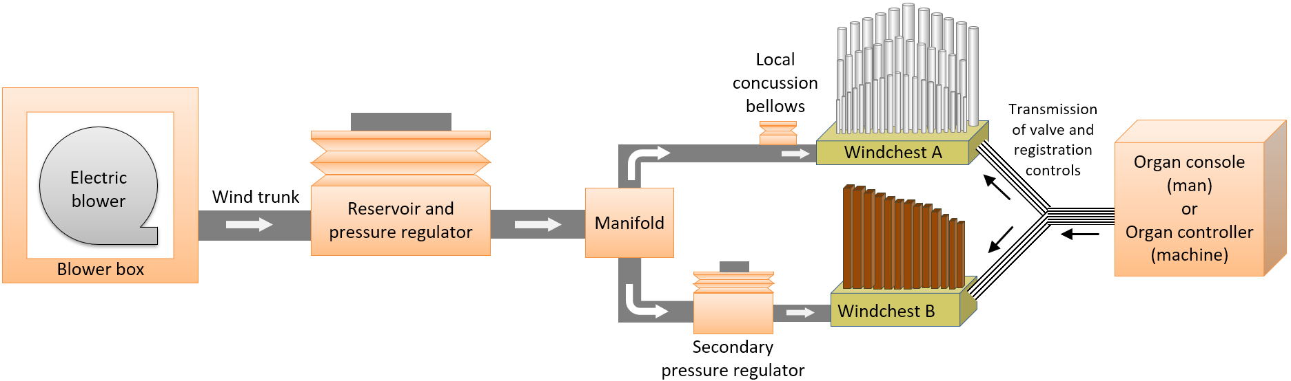
The illustration is based on the components in the EnsembleBot wind system and does not represent a “real” pipe organ in any satisfactory way whatsoever. But no matter how simple we make it, there are still some fundamental parts of any pipe organ that must be considered:
- A blower to produce the wind to make sound in the pipes. The blowers in modern organs are powerful electrical motor blowers.
- A pressure regulator to ensure a constant air pressure to the organ. The pressure regulator is usually a combination of some kind of bellows and an air reservoir. This is a very important component. Organ pipes are very sensitive to pressure changes, because they result in noticeable pitch shifts. The pressure must be held constant and compensated, and without a pressure regulator the pressure would change depending on which and how many pipes are playing at any given moment. The regulator is placed between the blower and the organ windchests.
- Air trunks to transport air from the blower to the regulator and to the windchests.
- A windchests under pressure with valves for letting out air into the pipes. The windchest itself is basically just an airtight box with a large air inlet from the blower/regulator, and a number of valves.
- Secondary regulation in the form of concussion bellows to reduce pressure transients or a secondary pressure regulator to supply a lower air pressure to parts of the organ
Then, of course there are all the valves and pipes and stuff inside the instruments, but that is described elsewhere. Now, of course, a real church organ has many more essential components, and each of them infinitely more complex and intricate, than we are able to design or make them.
BLOWER
Air flow is a measure of how much air is moved in a given time frame, and is usually measured in cubic meter per hour (m3/h) or cubic feet per minute (CFM). Without a decent flow, the pressure regulator’s air reservoir will be exhausted too quickly. The flow is, of course, dependent on which and how many pipes are playing at any given time – the air demand. When none of the instruments are playing, the demand will be zero. So, there are two important factors to consider regarding air flow:
- The blower system must be able to maintain an air flow high enough to be able to play enough pipes simultaneously without exhausting, and preferably with a decent margin. How many pipes and for how long should, of course, be a design decision. In our case, however, it’s more a matter of building a blower blindly, and then deciding afterwards if it is large enough…
- As it’s to be expected that the demand will be low or zero much of the time, while the blower is on, the blower must be designed to be able to withstand a constant flow of zero, comparable to completely blocking the wind output from the blower. If not, the blower might stall and/or overheat.
But the blower must also be able to maintain a high and stable air pressure, both when the organ is idle as well as when many pipes are playing at the same time. A pipe organ needs a constant pressure, e.g. around 3 inches of water column (3″ w.c. = 7,5 hPa = 76,2 mmH2O) above atmospheric pressure. Inches of water column is a traditional measure of organ air pressure, based on water levels in a U-shaped manometer.
Keeping a constant pressure is essential to ensure a steady tone from the pipes. Even slight pressure variations can be heard as changes in timbre and pitch. It’s also important that the organ is supplied with the same constant pressure every time, as each pipe is voiced and tuned to a very specific pressure. If the organ pressure changes, all pipes need to be re-tuned. But more about keeping constant pressures below.
Electrical blowers have been around for about a century, and modern pipe organ blowers are both strong, efficient and silent. However, these are not something you stumple upon every day in the second-hand market, and if you find one, it’s usually much too expensive or much too big for our use.
ENSEMBLEBOT SOLUTIONS

For our first test blower, the PipeWind v.1 we used small 24V blowers – first one, later two in parallel to satisfy the demands of the organs. These worked great for our test organs and even the PipeDream61, but as the instrument grew, we had to take it to the next level.
So, the PipeWind v.2 is based on a much larger blower for bounce houses. It was extremely cheap, has a respectable air flow, can keep a sufficiently high static air pressure and does not mind a blocked flow when the air demand is zero.
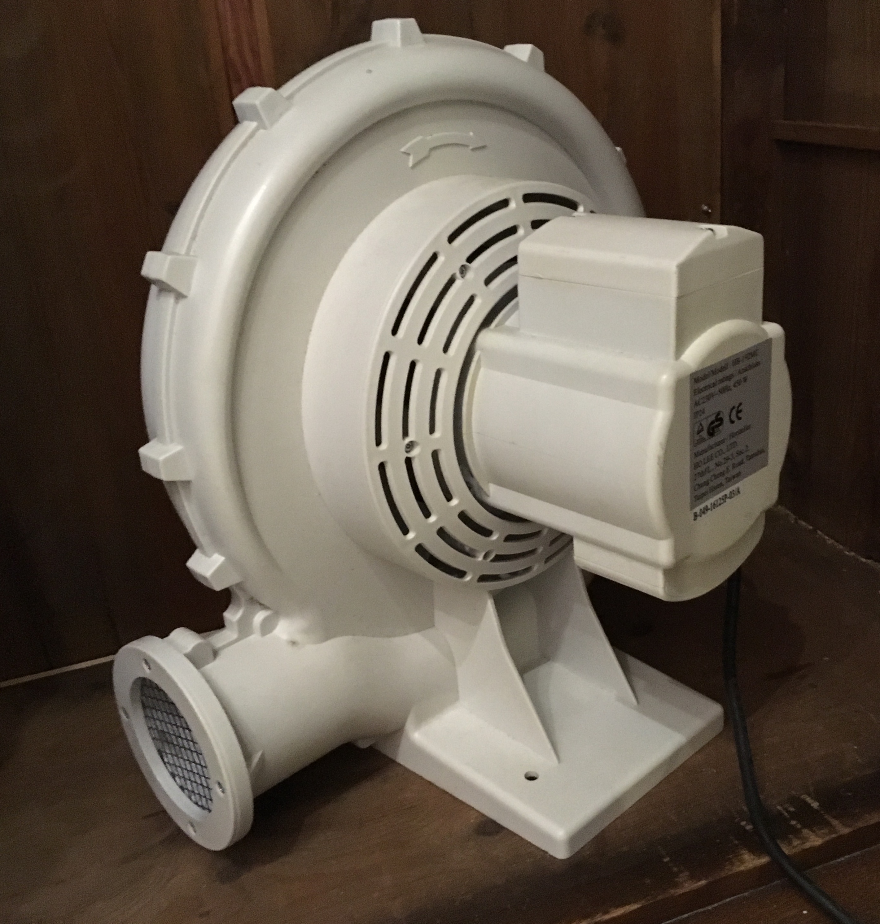
However, it is made of plastic and the words “silent operation” was probably not mentioned anywhere in its design specifications. It’s noisy as hell, so even with a lot of silencing, we’re going to have to physically place the blower in another room away from the organ.
Read more about how we deal with the blower noise in the PipeWind 2.0 page.
RESERVOIR AND REGULATOR
Even if a blower can supply a desirable static pressure, this pressure will change (drop) as soon as the pipes start demanding air. There will be nothing to ensure a stable pressure under all conditions. For this we need an air reservoir as a buffer and a pressure regulator to precisely control the pressure in the organ, no matter the air flow (i.e. how many or how few pipes are speaking).
Why not just adjust the blower power/output, instead of building a pressure regulator? Pressure sensors are quite fast, precise and easy to use these days, and most electrical motors can be easily regulated. Well, the main reason is latency. While a sensor can detect a pressure change and adjust the power of a blower within milliseconds, the blower itself will be much slower to react, and the result will be unacceptable pressure fluctuations in the wind system. A physical pressure regulator has by design a much better reaction time.
There are many ways to build a pressure regulator, but most of them are implemented as some sort of bellows, either spring loaded or weighted. The air from the blower enters the reservoir and extends a rather voluminous bellows. The strength of the springs or the weight on top of the bellows determines the desired air pressure. Stronger springs or heavier weights means a higher pressure is needed to raise the bellows, and when air demand is high (i.e. higher than the blower can deliver, at least in the short term), the collapsing (deflating) bellows will still exert this exact pressure.
STATIC PRESSURE VALVE
A blower is by definition able to supply a static air pressure higher than the desired organ pressure. This means that the bellows of a passive organ would keep expanding until it reaches an extreme position, where the spring force or weight no longer has an effect. This is, of course, not a desirable situation. So, to make sure that the static pressure is the same as the active pressure (i.e. the pressure when air is flowing), some kind of static pressure valve is needed.
As we can’t rely on blower control for this, as mentioned above, there are basically two ways of doing this: curtain valves and exhaust valves.
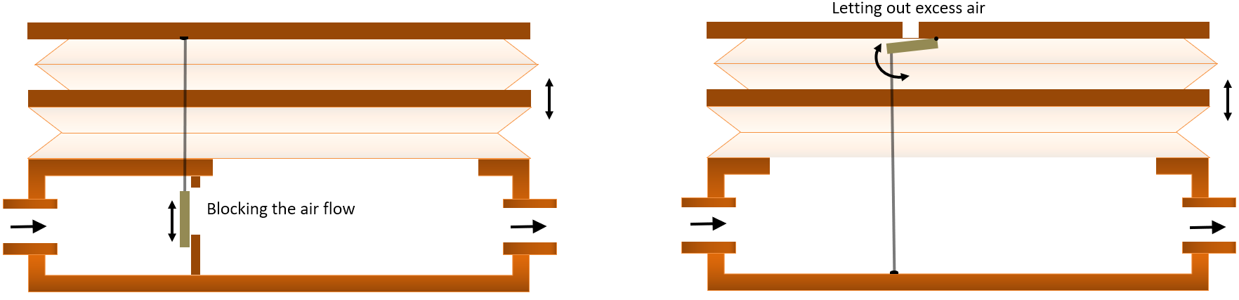
Curtain valves are neat mechanisms, illustrated above. As the bellows expands towards its extreme (expanded) position, a system of rods, strings and/or pulleys pull a curtain in front of the air intake from the blower, thus directly blocking the air flow into the reservoir/regulator. The system will reach an equilibrium before it reaches the extreme position of the bellows. Here the curtain valve reduces the air flow just enough to prevent the bellows from extending further. Though quite complicated, curtain valves are by far the most popular static pressure valve type.
An alternative solution is to use an exhaust valve. The goal is the same, but instead of restricting air from the blower, the extending bellows pulls open a valve venting excess air to the atmosphere. This is an extremely simple construction, as it is basically a valve inside the reservoir/regulator, coupled to the raising bellows. When the bellows nears its extreme position, a piece of string begins to pull open the valve. That’s it. Very simple, but arguably more noisy than a curtain valve.
Guess which of these two options we went for? Right. The easy one. Now, although the exhaust valve solution is less elegant and much less scalable and sensitive, it does have a small advantage. Where the curtain valve potentially blocks the airway of the passive organ almost completely, the exhaust valve actually lets out more air the more the organ becomes more passive. Using an electrical blower that is not designed and built as an organ blower, it might not be as happy to operate with a completely blocked outlet for longer periods of time, and the exhaust – however minimal – could be just enough to provide some air cooling to the blower motor.
BELLOWS FORCE
The weighted bellows is arguably the simplest and easiest, both to build and to adjust, but it comes at a price. A bellows with perhaps 5-10 kg or more weight on top of it introduces a sizable intertia. The larger the intertia, the slower the bellows will react to pressure changes.
Spring loaded bellows, on the other hand, are much more spry and precise. However, they can be quite complicated to build and adjust, using a set of adjustable pantograph springs, as indeed many great organs do, though far from all. Many organs opt for a much simpler and uncompensated design with simple expansion springs.
Weighted bellows have a clear advantage besides simplicity, and that’s a very linear response. If built properly, a weighted bellows exerts the same backpressure no matter how extended or compressed the bellows is. This is not the case with a bellows using expansion springs. In principle, a springloaded bellows only keeps the intended pressure at one precise expansion level. So, all other things being equal, a simple weighted bellows will potentially keep a more constant pressure than a simple springloaded bellows, with the possible exception af a well-designed and -adjusted pantograph spring that reduces the effect of non-linearity.
IN A PERFECT WORLD…
Ideally, a spring loaded regulator would be made with folded bellows in reverse fold-pairs. With reverse folding, the volume response is directly proportional to the bellows expansion, because as one bellows-fold contracts with expansion, the other expands. If both folds either expanded or contracted, the expansion would be non-linear, especially when close to deflated.
To ensure equal volume expansion between the two folds, the layers of the bellows is coupled with Z-type or scissor-type pantograph expansion guides, making the folds expand and contract in perfect synchronization.
ENSEMBLEBOT SOLUTIONS
The EnsembleBot does not live in a perfect world. In PipeWind v.1 we made a very simple wedged sack bellows with exhaust valve and about 5 kg weight on top to achieve a 70 mmH2O pressure (appx. 3” w.c.). It actually worked suprisingly well, once the worst leaks in the air system were patched up. However, the reservoir and regulator bellows volume was barely enough for the PipeDream61 organ, and certainly not enough for a growing number of air-hungry instruments like the Zimbelstern and the PipeMare instruments.
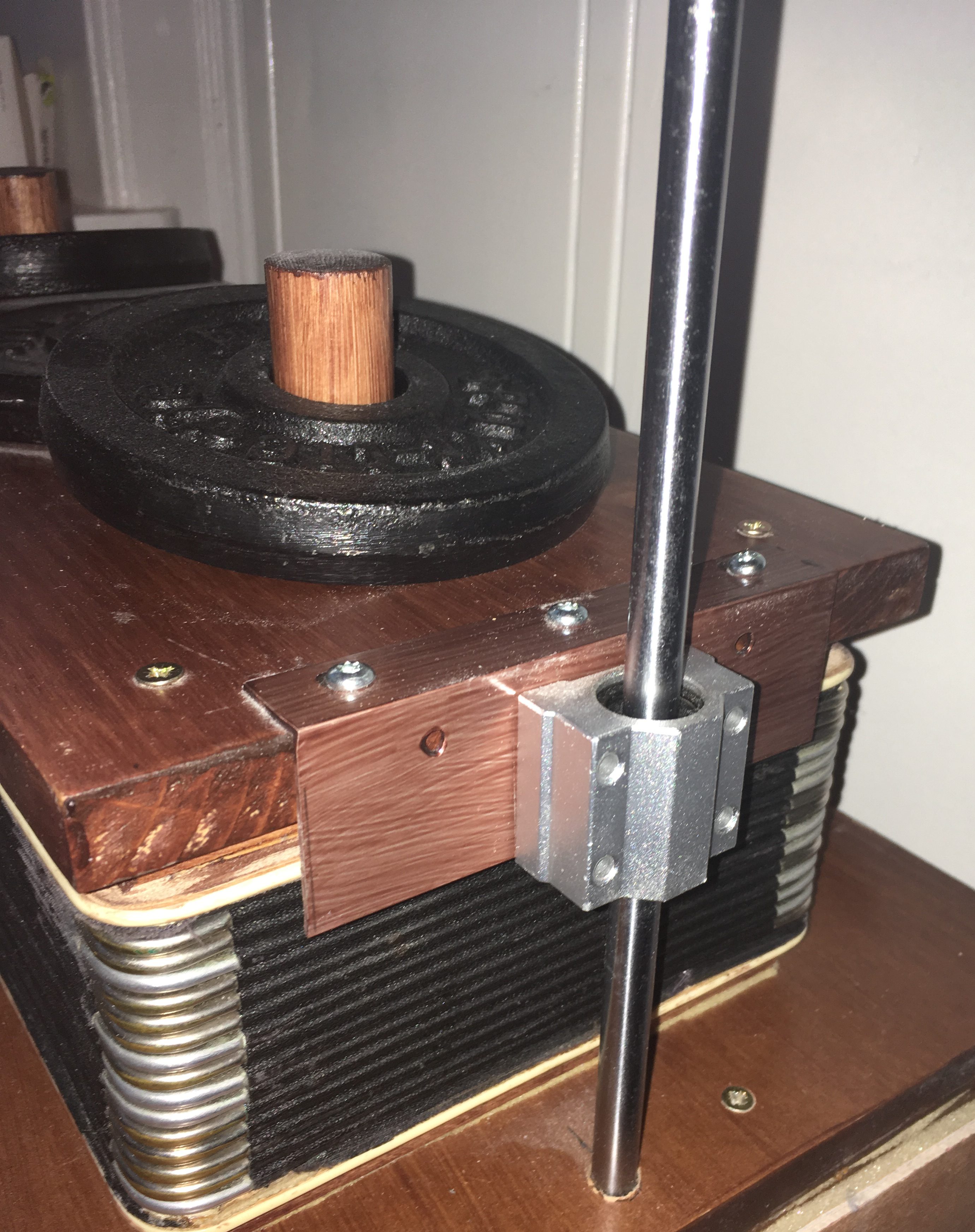
In PipeWind v.2 we built a larger reservoir, and made sure in our design, that the initial bellows/regulator could be replaced by a better design, if it wasn’t good enough. For now, the bellows is actually the bellows from the deconstructed accordion in PipeMare, turned on its side and with some heavy weights on top.
The volume may not be large enough, and the bellows might not be responsive enough, but it looks cool. If it turns out to be insufficient, we’ll have to build a better bellows, probably like the reverse fold bellows shown above, and maybe even with a curtain valve. Could be fun.
The regulator has a built-in exhaust valve to keep a static pressure level. The valve is simply a spring loaded pallet valve on the inside of the top-piece of the bellows. A piece of string starts pulling the valve open, when the bellows is nearing its maximum allowed expansion.
WIND TRUNKS
The ducts or tubes for transporting the pressurized air through the blower system from blower to regulator and on to the instruments are traditionally called wind trunks. In large organs they are large, fixed air channels, usually contructed of wood. The larger and more straight the windtrunks are, the less air resistance and the less pressure drop when the air flow is high.
Also, a large wind trunk will in itself act as a kind of secondary air reservoir, which can be a blessing as well as a curse. The large volume of air in the wind trunks can be a buffer against pressure changes. But with a too large and too long volume of air, the actual weight and compressiblility of the air introduces a measure of intertia and a risc of “bouncing”, where pressure waves move back and forth through the air trunk resulting in a fluttering sound. This is very similar to the ringing phenomena in unterminated electronic communcation busses or using cheap car shock absorbers with bad dashpots. The solution to ringing phenomena is to take the energy out of these pressure transients. In a wind trunk this can be done by introducing baffles along the wind trunk, but the cost is a higher wind resistance and a sizeable and problaly non-linear pressure drop as a function of wind demand.
Baffles reduce the larger and slower air bouncing, but these ringing phenomena are also present in smaller and faster scales inside the windtrunks. A better way to deal with that is to use concussion bellows close to the instruments. More about those in a moment.
ENSEMBLEBOT SOLUTIONS
Since EnsembleBot is a very small-scale and anything but permanent project, traditional permanent wind trunks are out of the question. We use a length of cheap 102 mm (4”) flex hose. The ridged walls on the inside of the tube introduce a substantial wind resistance, which must be taken into account when adjusting the static and active pressures. But this resistance, combined with the flexibility of the tubes, also reduces the risc of the larger/slower ringing phenomena. Well, at least that’s our working hypothesis, until disproved.
CONCUSSION BELLOWS
When one or more pipes are activated simultaneously, there will be a sudden pressure drop inside the windchest. This pressure change will inevitably result in a so-called step response (https://en.wikipedia.org/wiki/Step_response), where the change will reverberate or “ring” for a short time until settling. Depending on the initial amplitude, settling time and decay time, this ringing can result in very audible issues in the organ sound, ranging from weak fluttering to severe pitch changes.
As mentioned above, such phenomena are best dealt with by taking out the energy of the ringing. In digital circuitry you do it by placing a decoupling capacitor on each IC, as close to their power/ground pins. It’s in the very nature of digital components to have very sharp edges on their power demands, and the decoupling capacitor makes sure, that these sudden changes in power usage don’t momentarily exhaust the power lines resulting in brown-outs, or introducing noise to the rest of the circuitry, wreaking havoc elsewhere. And as mentioned before, it’s much the same phenomena we see in long communication busses, in the response of a car driving too fast over a bump in the road, and even in how heat propagates through a medium or in how the economy responds to sudden changes, and so much more. It’s within fields of study called Impulse/Response and Linear Response Theory, but however interesting that may be, it’s quite a digression. Sorry.
In organs we deal with ringing in the wind system by introducing so-called concussion bellows. These are much smaller bellows, than we have in the main pressure regulator, and they are placed as close to the windchest as possible, preferably as an actual part of the windchest. In larger pipe organs, it is not uncommon to have a large portion of the bottom of the windchest work as a concussion bellows. The bellows is usually built either as a simple hinged angular bellows (called a winker) or as a floating cut-out plate mounted with flexible leather, rubber or cloth (called a schwimmer). Concussion bellows are usully spring loaded, because a fast response is valued above linearity.
In contrast to the more complex pressure regulator bellows, a concussion bellows is a very simple and closed buffer. At normal (static) organ pressure, the springs are adjusted to place the bellows is in its middle position. This enables the bellows to move both ways, reacting to small and fast pressure changes, and hopefully (if dimensioned correctly) counteract and even absorb the transient pressure fluctuations and ringing.
ENSEMBLEBOT SOLUTIONS
As has been established, we are not organ builders, and we learn along the way. Unfortunately, we apparently learn stuff in the wrong order. So, as we built the PipeDream61 windchest, we didn’t even plan for a concussion bellows. Here we have 61+ pipes mounted on a smallish windchest without expansion chambers or anything. However, the simple design of the windchest makes it possible to actually cut out a schwimmer in the bottom of the windchest and raise the windchest to allow for bellows expansion and springs. An alternative solution would be to place a small winker bellows just outside the air intake to the windchest.
Later, while designing the PipeMare instruments, we knew of the potential need of concussion bellows, but we realized, that because of spatial restrictions we couldn’t possibly fit them into the windchests inside the cabinet.
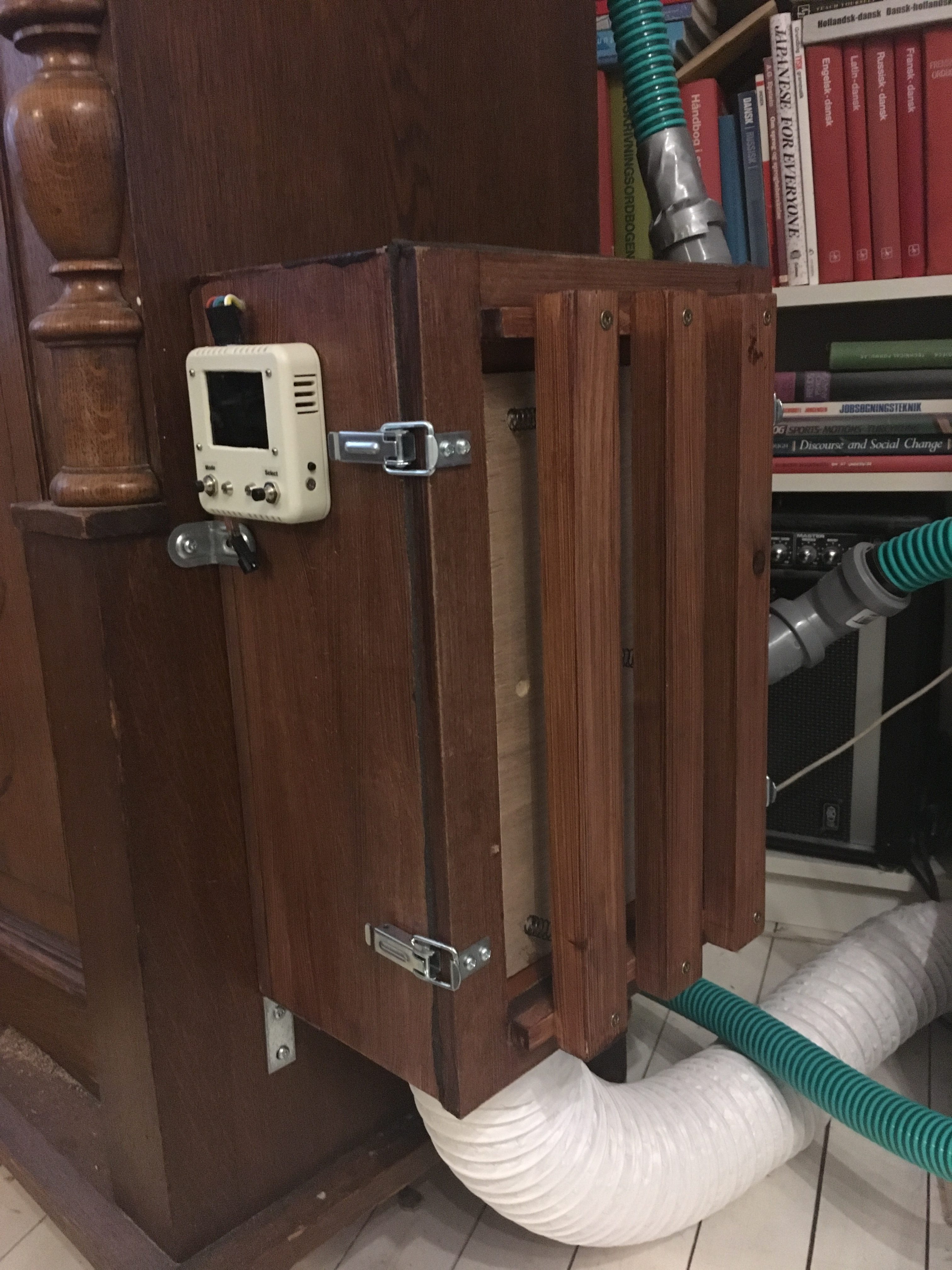
The solution (so far) was to build a scwimmer into the air manifold, that we were going to build anyway. As mentioned above, the air from the blower is transported in a 102mm (4”) flex hose, but we have presently 4 windchests to feed. So, we designed a small manifold on the side of the PipeMare cabinet. This is basically a box with a mount for the 102mm flex hose at the bottom and a number of sockets for smaller (40mm) tubes to the individual windchests. Building a concussion bellows into this manifold reduces a lot of the transient pressure problems in the major wind system, but it has yet to be determined, if it also helps with the more localized needs in the windchests. The distance from the manifold to the windchests in the PipeMare cabinet is quite short (1-3 feet) and perhaps that is short enough to notr cause trouble. But the PipeDream61 windchest is placed several meters from the manifold, and so will probably not benefit at all from the manifold concussion bellows. Time will tell.
SECONDARY PRESSURE REGULATOR
While both the PipeDream61, the PipeMare Piccolo and the PipeMare Accordion work comfortably at a pressure of 3” w.c., the PipeMare Flutes are designed for a 2” w.c. pressure. Having them work at 3” will severely overblow them, resulting in awful and quite unacceptable sounds. Currently, there are two possibilities:
- Reduce the organ pressure to a level between 2” and 3”, where all pipes sounds acceptable
- Introduce a secondary pressure regulator between the manifold and the flute windchest to reduce the 3” pressure to a 2” pressure for the flutes alone.
Currently, we have not had the opportunity to test the first (and obviously easiest) solution. We know, that the PipeDream61 organ can work quite well at lower than 3” pressures. But it is much more doubtful if the harmonic piccolos in the PipeMare cabinet can work at lower pressures, as they by design must overblow – the very property we want to avoid the the flutes.
If it turns out, the we need to run the primary wind system at 3”, then we build a small secondary pressure regulator for the flutes. It will be much like the major regulator, but it has to be built with a curtain valve, and not an exhaust valve (see above). An exhaust valve will constantly drain the wind system for air and it will be too noisy.
However, having a weighted bellows, even a smaller one, might make the need for another faster concussion bellows inevitable.
PRESSURE ANALYSIS
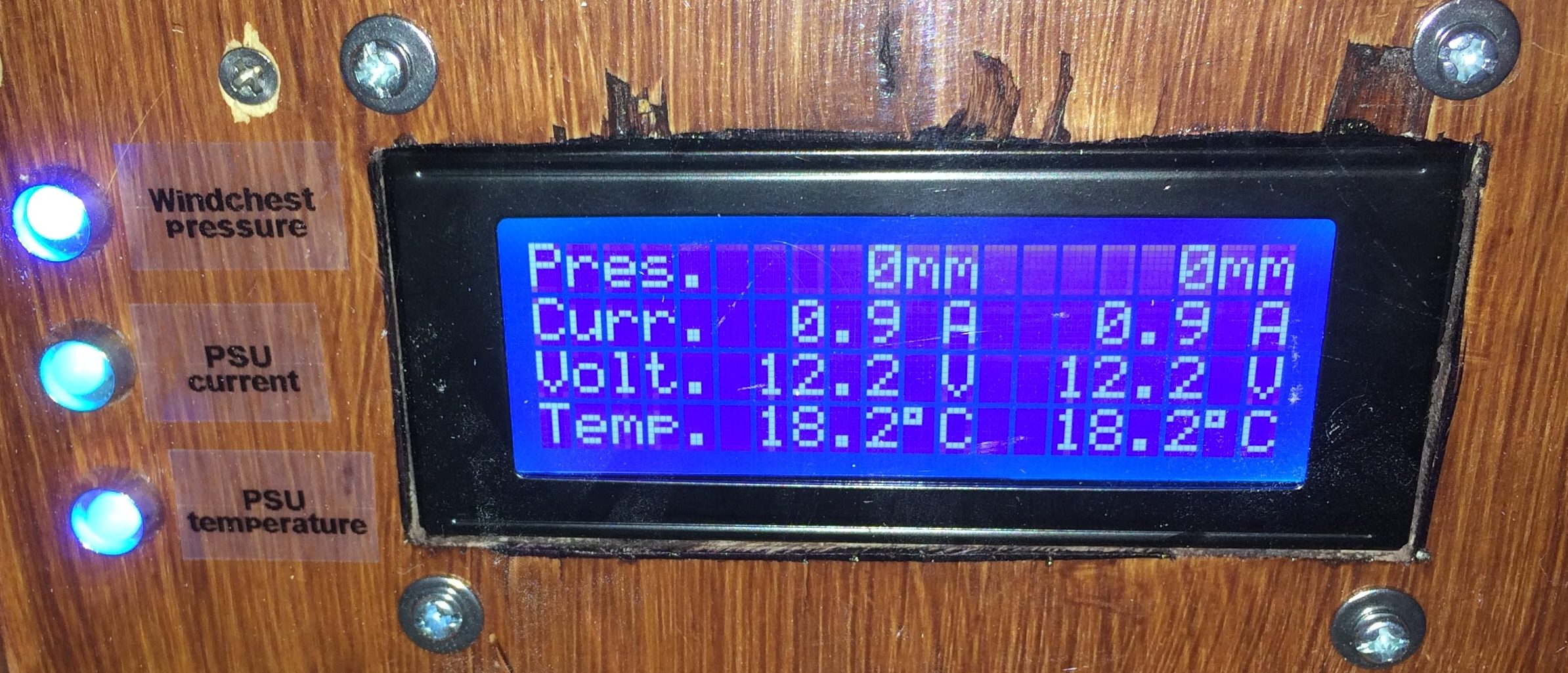
In the PipeDream61 organ we have a built-in pressure sensor. Besides monitoring the pressure in the winchest, we also used it to adjust the static pressure of the PipeWind 1.0 wind system. It nice to know the exact pressure to ensure correct tuning, but this very basic monitor is not good enough to provide any detailed analysis of the pressure and impulse/response characteristics of the wind system.
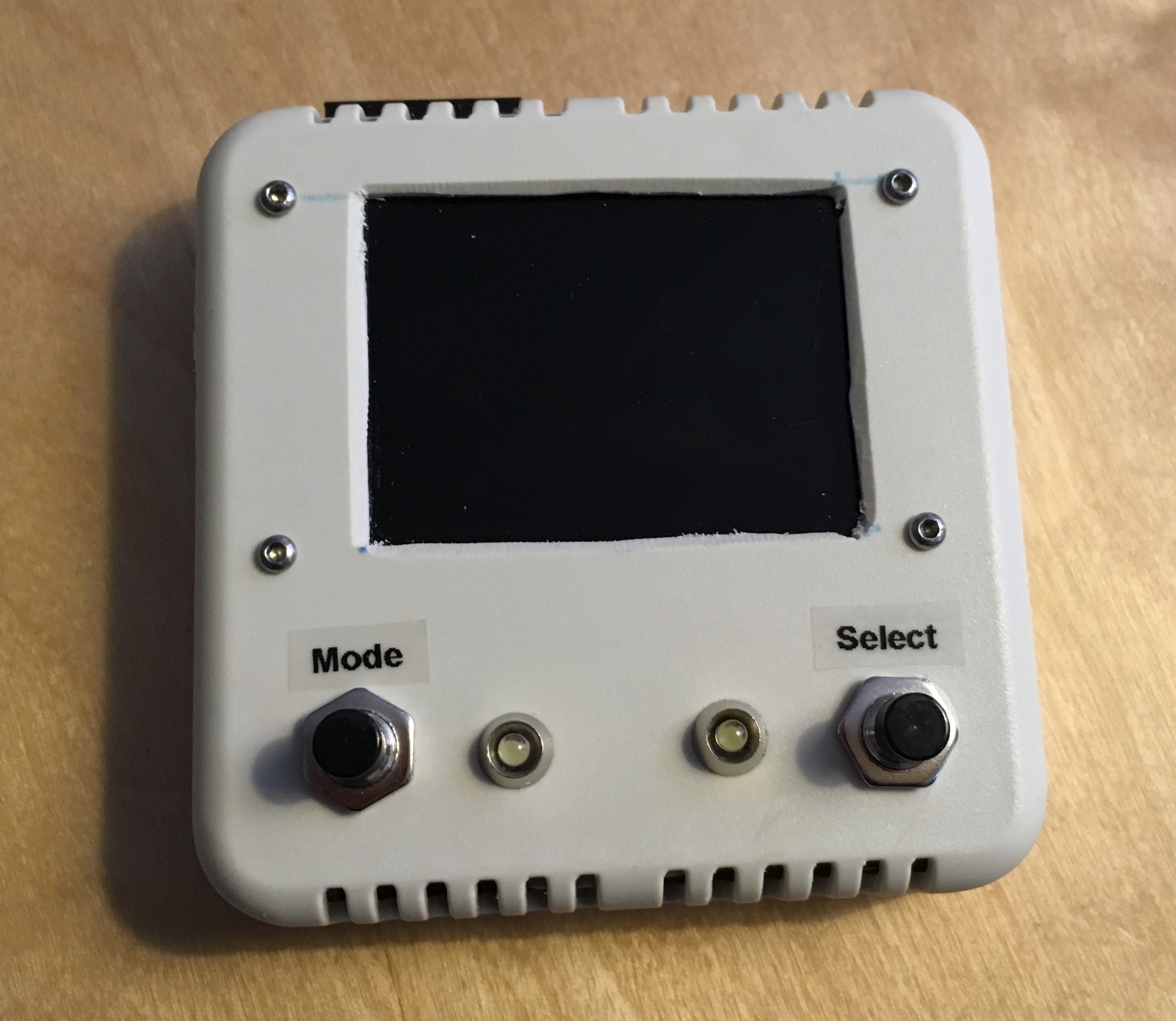
As the need for such analysis grew with the introduction og PipeWind 2.0 and the PipeMare instruments, we decided to make a better tool for pressure monitoring and analysis.
The monitor is placed on the manifold with a sensor both inside the manifold and outside (to correctly compensate for atmospheric pressure).
The device will in normal operation provide a live feed of the air pressure, but can also be used for detailed analysis of pressure responses by doing a burst of 100 measurements pr. second for 3 seconds, and subsequently showing the response on the TFT screen of the device.