
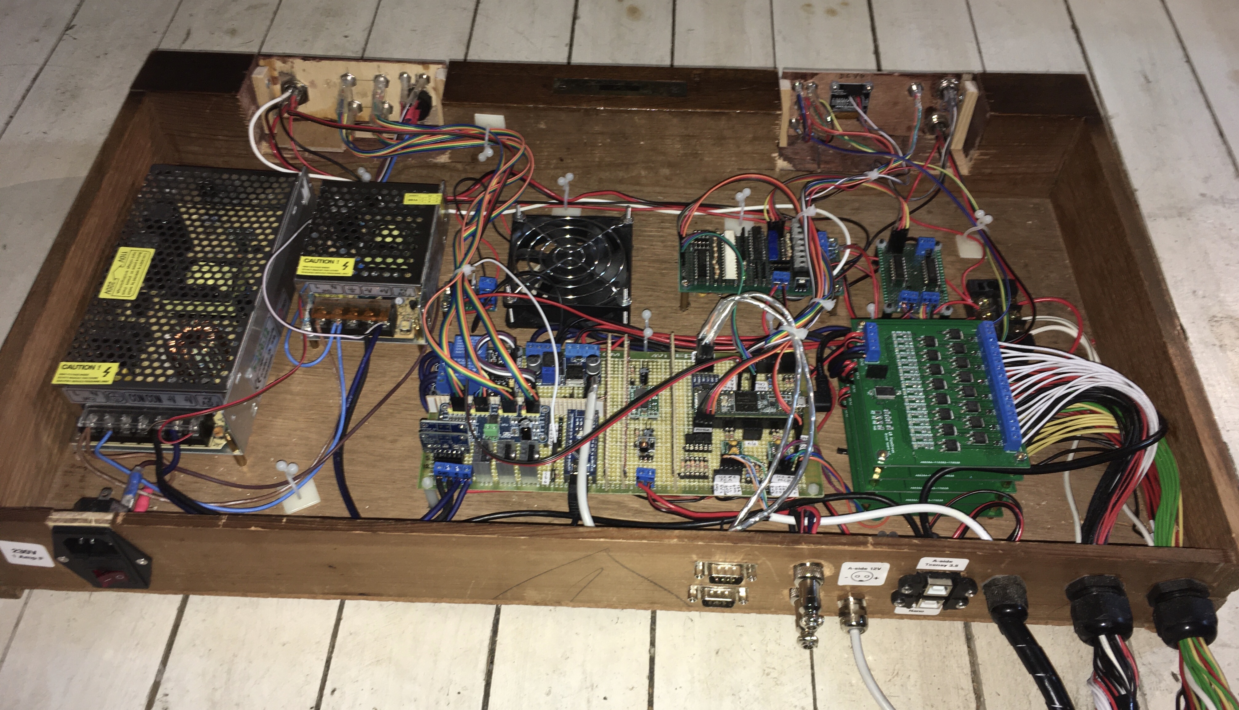
The PipeMare will work as three separate instruments (plus extra functions like swell panels), but to keep the hardware simple, they will all be controlled by the same controller. Because the PipeMare cupboard may be placed far away from the EnsembleBot master circuitry and power supply, we use local power supplies for the organs valves and servo motors.
Project status: Under construction. Assembling the pipe driver boards is next up.
POWER AND DOMAIN ISOLATION
Powering the PipeMare is pretty straight forward, but as with all our EnsembleBot projects we enforce a strict isolation between the A-side power domain (microcontrollers, CAN-bus, USB host etc.) and the B-side power domain (motors, solenoids, magnets, servos etc. – i.e. noisy components).
The A-side will most likely be powered directly from the central EB Power Supply as the power demands are very small (a microcontroller, a CAN-bus driver and a few supporting components).
On the B-side, however, we’ll need som more power. The 44+31 pallet valves need 12 V, while the 46 servo motors only need 5 V. We could use a single 12 V PSU and a powerful step-down converter (buck) to make 5 V, but it’s much easier and not much more expensive to just use a separate 5 V PSU.
To keep track of the power usage and the temperature of the top drawer we dedicate a microcontroller to this task alone. A small Arduino (Nano, Micro or similar) will constantly monitor the current and voltage levels of the two PSUs using INA219 high-side current sensors, and – if necessary – cut the power using a dual relay module. This MCU will also check the temperature and turn on a cooling fan if needed. As a third function it will “send back” two TTL level signal to the A-side through a pair of optocouplers. These will be read by the central instrument controller MCU as an indication of the status/health of the B-side power domain.
To talk across the domain barrier, we use I²C isolator chips (Texas ISO1540, Analog Devices ADuM1250 or similar). We’ve used them in several other projects, including PipeDream61, and they work perfectly. All the simpler TTL lines for control of B-side components (swell door motor, LED illumination etc.) will be isolated with simple optocouplers.
CHOOSING A MICROCONTROLLER (MCU)
When designing a controller circuit, there are basically two ways to approach this complex instrument. One way is to treat the three organ parts as three independent (slave) instruments, each connected to the EB Master circuit via the CAN bus. Another way is to treat the cupboard as one single, complex instrument with a central controller. A single, central controller would have a lot of work on its hands, but it would definately make the total circuitry much simpler. So that’s the way we go.
TEENSY 3.2 ?
If we go with the single controller approach, we’d need a pretty powerful MCU to handle all the ports and timings, as well as parsing the EBP communication over the CAN bus. In PipeDream61 we used a Teensy 3.2 microcontroller, which is a Arduino IDE compatible 72 MHz unit with much more RAM (64 kB) and flash memory (256kB) than, say, an Arduino Uno (16 MHz, 2kB RAM, 32 kB flash). A Teensy 3.2 would be more than enough in terms of raw speed and computing power.
CROWDED I²C BUS
Both the accordion with its stack of PCA9685 PWM drivers and the two pipe chests with MCA23017-based valve drivers are based on the I²C bus.
Even if we take advantage of the two separate I²C busses on the Teensy 3.2, we may still be facing some serious problems. The I²C bus is designed for quite short range communication between very closely placed circuits. Here we are placing many devices (including the Teensy master and the bus isolator) on each bus. Even if we place the I²C slaves devices fairly close together, the resulting total bus capacitance might well prohibit fast bus speeds, limiting us to a slow bus at 100 kHz (or possibly lower). In a simpler instrument this wouldn’t pose much of a problem, but when more than 10 I²C slave devices must be addressed from the same master, overall bus/slave latency suddenly becomes an important factor, and going from standard speed (400 kHz) to e.g. 100 kHz can make the difference between succes and disaster.
However, we propose to place the five MCP23017 I/O expanders (pipe drivers) on a bus of their own. MCP23017 can in principle work very fast with bus speeds of up to 1.7 MHz. Although we won’t acheive that speed, working at 1 MHz or even a solid 400 kHz should be nice and simple, especially if we place the driver stack physically close to the MCU.
Then we place all the PWM drivers on the other bus. The PCA9685s are very tolerant, indeed, apparently accepting up to 4000 pF total bus capacitance. So, the limiting factor will most likely be the I²C isolator output. The ISO1540 accepts a general maximum output capacitive load of 400 pF, whereas the alternative ADuM1250ARZ is more sensitive with a maximum capacitive load of 120 pF @ 400 kHz (or 484 pF @ 100 kHz). This may even be tolerant enough that we can move the PWM drivers away from the Teensy master and into the harmonica windchest using a piece of CAT5e cable. Assuming a 10 pF capacitance for each of the four PCA9585s and approximately 50 pF for a 3 ft piece of CAT5e, then it might work, even when factoring in some stray capacitances.
As mentioned above, the response times of the micro servos are already a bit problematic, so even if we are forced to operate the PWM drivers at 100 kHz, it may not be noticeable. We don’t have a logic analyzer, so we’ll have to try it out to know for sure.
But we would like to put even more devices on the I²C busses, like an LCD display for feedback during tuning/calibration. This is not really an option with only two I²C busses if we want to keep the bus capacitances down. We’ve already moved functions like current sensoring, pressure sensor, and temperature sensor to separate dedicated MCUs, an still we need more I²C busses. Well, one more.
TEENSY 3.5
So, there are two possibilities: Using an I²C switch/multiplexer (like the TCA9548) or upgrading the controller MCU to e.g. a Teensy 3.5 with four I²C busses. The multiplexer is easy to use, but has a small timing-cost while changing active bus and (more importantly) has a maximum bus speed of 400 kHz or the slowest device on the multiplexed busses, i.e. bus speed is determined by the weakest link. The Teensy 3.5 on the other hand is cooler (120 MHz and lots of busses and I/Os), but more expensive. But cooler.
But seriously, besides the I²C busses, we are going to need quite a lot of general I/O ports, and the Teensy 3.2 just don’t have enough (easlily) accessible ports, unless you count the annoying bottom pads.
THE PARTS
A Teensy 3.5 setup could look like the block diagram shown below. The Teensy controllers are all powerful enough to easily handle all these devices, especially the 3.5 with its 120 MHz, so that’s not an issue. It’s just a matter of programming.

Here we’ll go through the major parts of the PipeMare controller circuit, as shown above.
(0) THE CENTRAL MICROCONTROLLER
Well, duh! We’ve already discussed this above. It’s the brains of the operation, controlling most (though not all) of the functions, including :
- Receiving and parsing EBP/MIDI commands from the EnsembleBot master controller via CAN bus
- Driving the pipe valves of 44 + 31 pipes and keeping track of heating/cooling parameters for each pipe (1)
- Driving the servo motors for 12 + 34 microservos in the accordion (2)
- Driving two DC motors for the swell panels via half-H bridges (4)
- Giving a running status read-out to an LCD display or similar (3)
- Managing PWM-controlled LED illuminations of each of the three instruments in sync with the music (4)
- Receiving basic 2-bit status from the secondary controller (6)
- Plus miscellaneous user inputs and feedbacks
(1) PIPE DRIVERS
In the PipeDream24 and PipeDream61 organs we designed special controller circuit boards to handle the heavy load of the linear solenoids valves. Those stackable circuit boards were based on MCP23017 16-port I²C I/O expanders, and since we needed two ports per valve, one board could only drive 8 pipes.
Now, classic organ magnet pallet valves has a much higher impedance than the linear solenoids, and thus a much lower power consumption, typically 100-150 mA. This lower current also means much lower heat dissipation in the coils and no need to worry about overheating the valves.
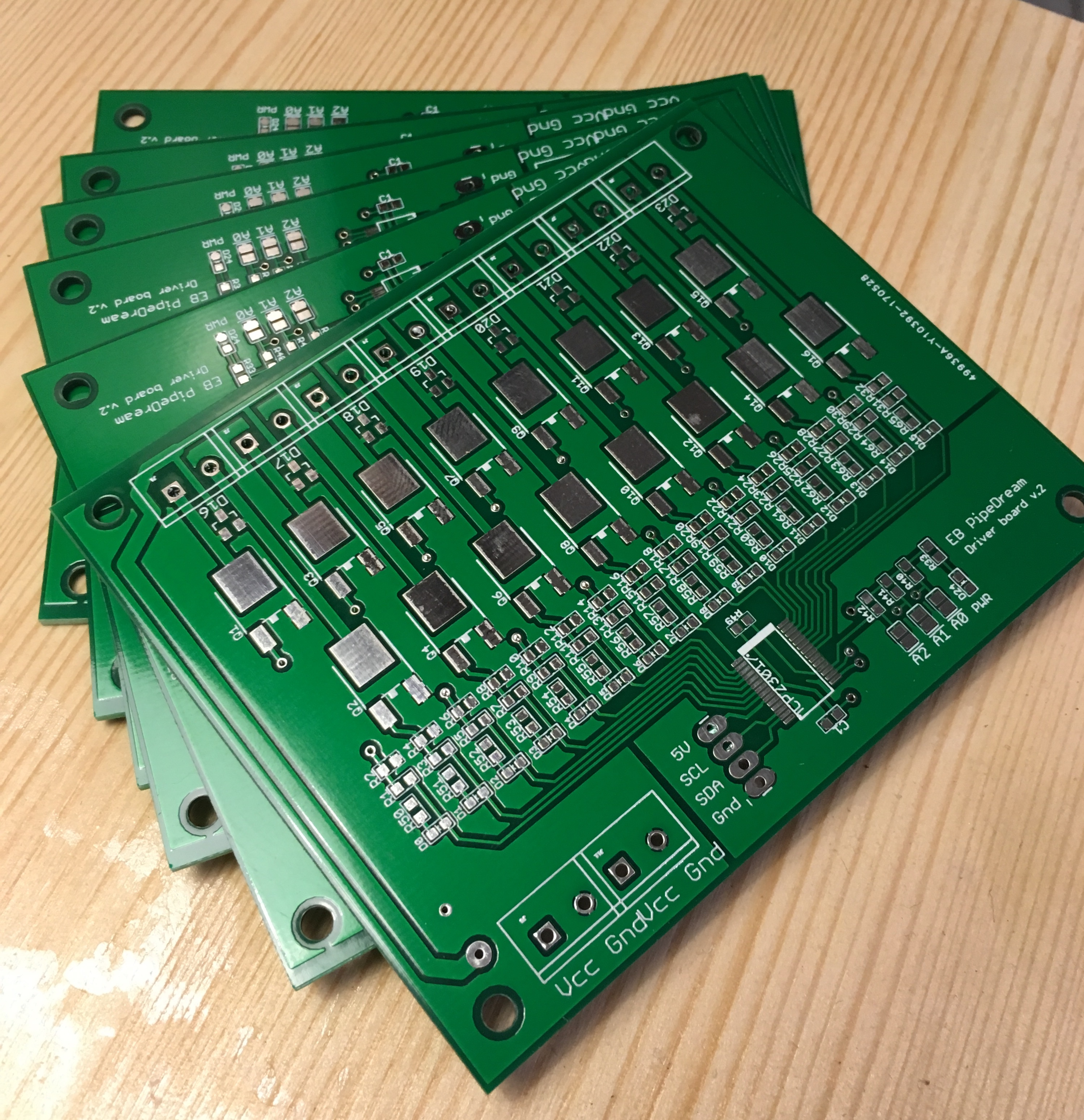
So, for this purpose the PipeDream driver boards would be absolutely overkill, and we designed a new and better driver board. These boards are only half the size of the old boards, but has 16 valve driver ports each. Like the old boards they are stackable for compact design and short I²C bus lengths, supporting up to 8 boards and 128 pipe valves on a single I²C bus. They are based on MCP23017 I/O expanders and IRLR2905 logic level N-channel MOSFETs.

The PCBs were manufactured in China to our design and specification. Again, the quality is very high, and again, it does come as a surprise that this solution is not only an easier option with a much better looking result, than if we had to expose, develop, etch and drill our own boards ourselves, but also a significantly cheaper option. Except for the connectors and screw terminals, all components are surface mounted (SMD).
In PipeDream61 we needed a full stack of 8 boards to drive the 61 + 3 valves. In PipeMare we’ll only need 5 half-size boards to drive the 44 piccolos and the 31 flutes. And we even have 5 driver ports to spare.
(2) ACCORDION DRIVERS
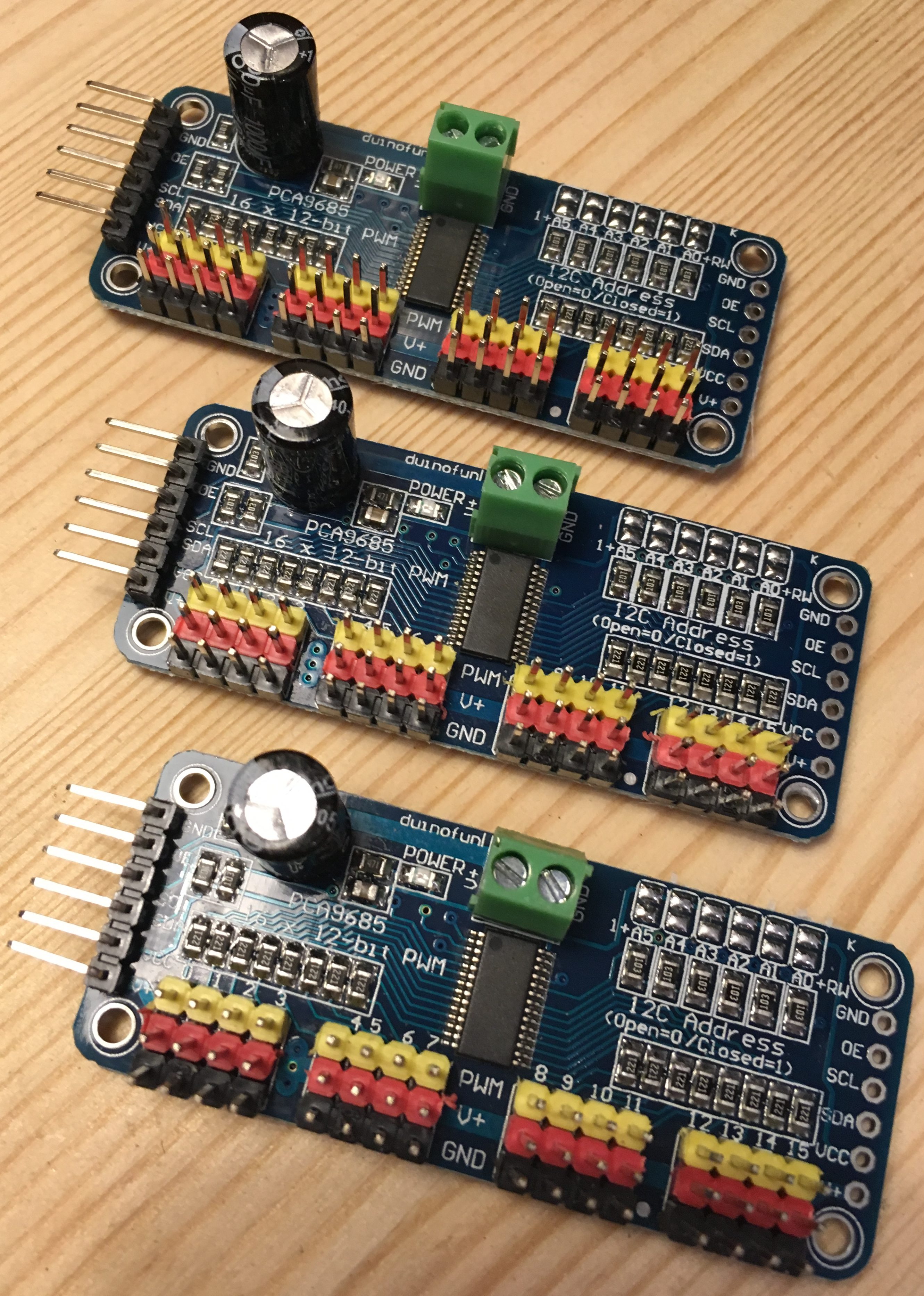
The accordion drivers are the basic 16-channel PCA9685-based PWM drivers, that are quite cheap. They are perfect for controlling servo motors.
They do, however, pose a problem. Either we’ll have to place these driver boards inside the top drawer of the cabinet with all the other electronics, or place the inside the accordion enclosure close to the microservos. With the first option we’ll have to have one cable per microservo (46 in total) leadning out of the cabinet and into the accordion enclosure above. The other option is to extend the I²C bus and lead that up into the accordion. As we have a dedicated I²C bus for these drivers alone, we’ll go for the second option.
(3) EEPROM module
As described in the PipeMare Accordion page, we are placing an I²C EEPROM module (AT24C256) inside the accordion, storing instrument calibration data.
(4) TTL CONTROLS FOR THE B-SIDE
The main controller controls a few simple devices powered on the B-side power domain. The two swell door motors are driven by half-H bridge drivers, needing only simple TTL signals to control. In principle, each motor is controlled by three signals: Input 1, Input 2 and Enable. In this setup, Input 2 will always be inverted signal of Input 1, and so we can “cheat” by using an inverter gate (74HCT14) on the B-side. This means we only need 2 signals per motor, and 4 TTL signals in total.
We are going to need optocouplers for each signal line. Fortunately we can repurpose an old 10-channel optocoupler array, so I don’t have to build new ones. But we still need to keep the number down, mainly because we are quickly running out of digital I/O pins on the Teensy controller.
(5) TTL SIGNALS ON THE A-SIDE
We are also going to need some TTL devices on the A-side, i.e. devices that are not connected to or dependent on anything happening in the B-side power domain. These devices are connected directly to the Teensy controller.
- We’d like an RGB LED for basic low-tech feedback on controller operation and status
- The swell doors each have two boundary switches to signal when the door is completely open or closed. This is done with simple microswitches. Using the NC (= normally closed) pins of the switch and internal pull-up in the I/O port, we’ll have a double safety feature, as a cable defect between the switch and the controller will trig the controller input.
- To manually control or override the swell doors (as opposed to have them controlled through the music/MIDI), we also want two non-latching (ON)-OFF-(ON) toggle switches.
- If we are going to make some kind of calibration modes, like in PipeDream61, we are perhaps going to need a few user inputs (unless we can re-use the swell door override switches mentioned above), but currently we are not planning to implement a calibration mode.
(6) SECONDARY MICROCONTROLLER
As shown in the block diagram above we place a secondary microcontroller on the B-side. This will most likely be a simple and cheap Arduino Nano. It’s responible for constantly monitoring the well-being of the power supplies and controlling the temperature of the drawer with all the electronics. Using INA219 current sensors, it constantly checks the voltage levels and current usage of the 5 V and 12 V power lines. In the event of critical levels, it can cut the power using relays. This might be a bit paranoid, but fun to design and build.
Another function is to send back a simple status of the two B-side power lines to the A-side central controller through a pair of optocouplers. This is a much more reliable way of testing for B-side power from the A-side. Alternatively we would have to test for B-side power by e.g. polling the I/O expanders to determine if they are responding or not.
If we want more status information on the B-side power situation, we could use another I²C isolator and use the secondary microcontroller as a I²C slave on bus #2, but that probably won’t be necessary. Two simple TTL levels to indicate if the power level is OK or not will suffice for now. TTL signal also have the distinct advantage that they are read by the main controller without delay, delegating the actual work load of monitoring the system to another controller.
(7) POWER RELAY
If too much power is drawn from the instruments, or if the controller temperature is too high, the secondary controller can switch off the two B-side power supplies (5V and 12V). This is done with a pair of 5V relay modules.
(8) TEMPERATURE SENSOR
To check the temperature inside the cabinet drawer holding all the electronics, we use one or more Dallas DS18B20 temperature sensors. We’ve used them before, and they are both reliable and easy to use.
(9) COOLING FAN
The cabinet drawer holds both the powerful 120 MHz Teensy 3.5, a stack of 5 x 16 MOSFET drivers for the pipes and two DC power supplies (12V and 5V) for the B-side. We are definately expecting the temperature to rise, so we might as well build in a cooling fan from the start.
The fan (or fans) will be turned on and off by a simple MOSFET driver controlled by the secondary MCU.
(10) RGB LED READ-OUTS
RGB LEDs are easier and faster to read, if you just need a simple indicator for a basic level. So, we use them to indicate the health of the power supplies and the internal temperatures of the drawer.
Driving 3-4 RGB LEDs would use up more PWM-enabled I/O pins, than are available on the Arduino Nano, so we use another of the standard PCA9685-based 16-channel PWM drivers.
(11) B-SIDE POWER SUPPLY MONITORS
Finally, we place a INA219 high-side current sensor on each of the two B-side power supplies to closely monitor voltage and current levels.
(12) MAIN CONTROLLER DISPLAY
The value of this device is debatable. In normal operation, a display is more or less useless. It’s only when something goes wrong, that the display has a value. In the PipeDream61 organ we have a simple 8-digit LED display on the main instrument controller, showing a status on pipe driver heat build-up (not relevant in PipeMare) and very basic error messages. While more detailed error messages is indeed desirable, it may not be enough to justify using an LCD display. We may opt for one of the small 1″-ish 128×64 pixel OLED displays, or even a 128×32 pixel. They are easy to use and don’t take up much space.
(13) CAN BUS
The instrument gets its instructions from the master through the CAN bus. The Teensy microcontrollers have a built-in CAN controller, which we’ll use, but to interface with the physical bus, we need a CAN transceiver. We use a SN65HVD230, which can be bought as pre-assembled modules, and they work perfectly.
STATUS
[November 2019]
The controller circuitry is finally finished. However, we need to make som global changes to the EnsembleBot communication and power schemes, before we can even begin to perform unit testing of the controller hardware. So,a working organ is still a long way away.
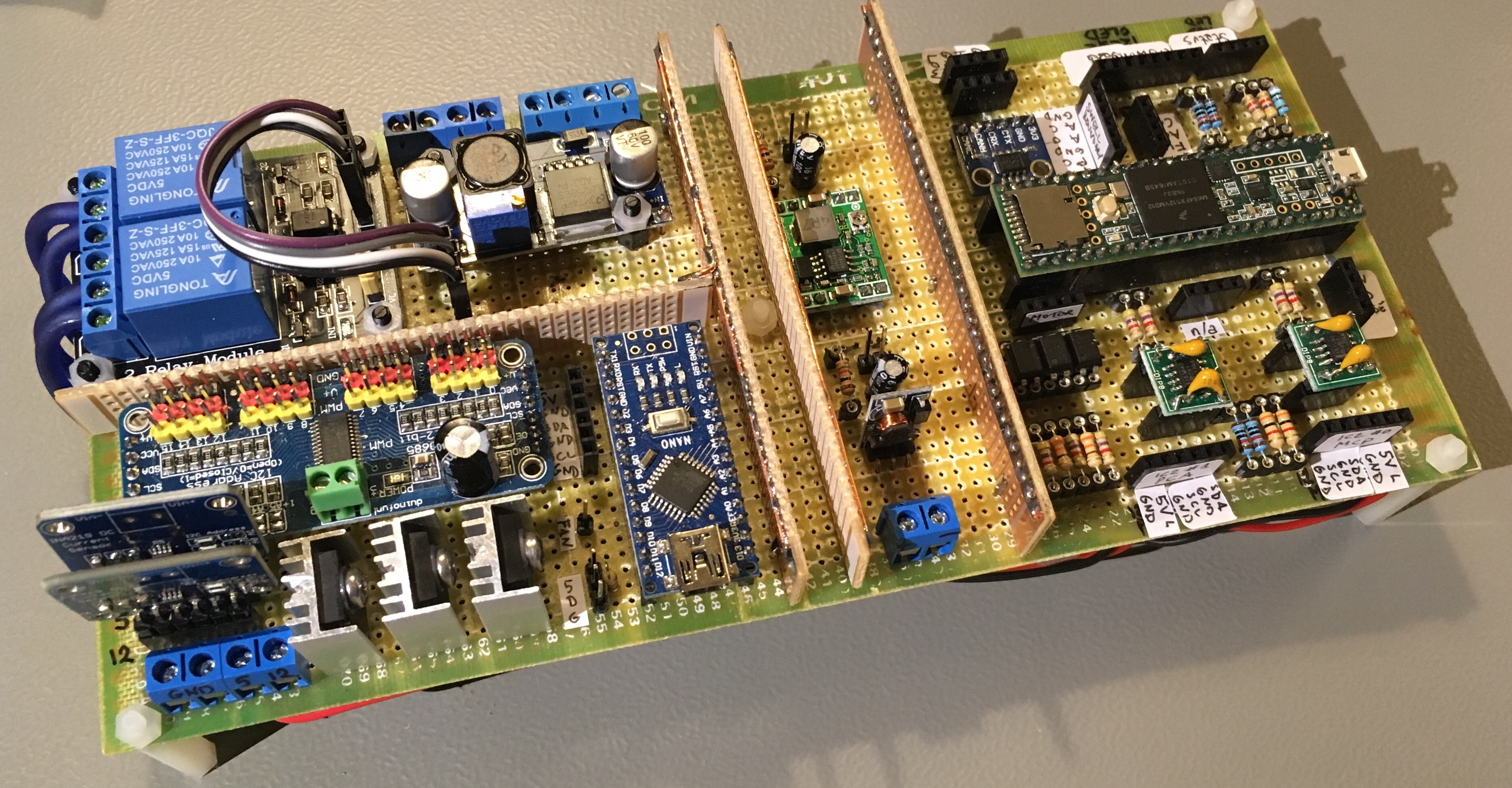
[June 2019]
Progress has been a bit slow, but now we are getting somewhere. The main controller board with primary and secondary microcontrollers has been assembled, though not yet tested.
The last two pipe driver boards need to be assembled, and then we can start assembling the complete PipeMare controller circuitry in the PipeMare cabinet drawer.
And then, of course, follows a very long, slow and tedious process of testing, debugging and correcting each of the one billion parts and functions in the instrument and the firmware.
[June 2018]
We have all the components, and slave firmware programming has begun, but there’s still a long way to go.