
PipeDream61 is our first major robotic pipe organ project, based on our experience with our test organ, the PipeDream24 – see this page for introduction to many of the concepts and solutions used in PipeDream61.

While based on our experiences with the PipeDream24 test organ, the PipeDream61 is both larger and better in almost every way. We reused many concepts in the new organ, while discarding, redesigning or improving other concepts. There are, however, still a lot of things to improve, and that will be part of the next organ project, the PipeMare project.
Instrument status: Finished and working
Here is a very early test. The pipes hasn’t been fully tuned or voiced:
VALVES
The valve system is basically the same as in PipeDream24, using the same cheap but very reliable Chinese linear solenoids. However, we have improved the actual valve pallets. Where the pallets in PipeDream24 were rather stiff, our new pallets are made with a layer of 4mm foam rubber and an even thinner and softer type of leather as the valve seal. This gives us a much better and more consistent seal as well as a more silent action of the valves.
We’ve also modified the actual solenoids slightly to make them more silent by inserting a very small nitrile O-ring inside the shaft frame. This greatly reduces the otherwise loud “clack!” as the shaft hits the bottom of the frame when actuated.
(THE LACK OF) EXPANSION CHAMBERS
While designing the PipeDream61, we didn’t know about the concept of expansion chambers. These are volumes of space between the valve and the pipe toe, small but still larger than both the valve hole and the toe hole, implemented as either an actual chamber or just a large air channel. The purpose of the expansion chamber is to buffer the abrupt inrush of air when the valve opens, and thus make the initial sound of the pipe more easy and free of stuttering.
In larger organs most windchests are slider chests or mixture chests, where the pallet valve lets air into a wind groove, through which air is let into one or more pipes, depending on selected stops. In such a configuration the wind grooves act as expansion chambers. But we are feeding each pipe directly with dedicated valves just below the pipe foot, having no buffer between the valve and pipe.
Had we known about expansion chambers, we probably would have tried to include them in our design, as our solenoid valve concept surely can use all the help it can get, when it comes to smoothing out its harsh actuation effects. But, alas, we didn’t know, and so we didn’t do it, and that accounts for some of the brutal sounds of the organ. Hopefully, we’ll have the opportunity to do it in a later organ project.
WINDCHEST AND TOEBOARD
We constructed the PipeDream24 windchest of the cheapest 18 mm pinewood boards, which made it ugly, light and leaky. This time we selected our materials a bit more carefully, though still trying to keep the cost down.

For uur new toeboard we used a 38 mm thick oak glulam board, which we were lucky to get very cheap.
The harder wood gives us a much needed precision and valve seal. The weight of the board will also help to absorb some mechanical noise.
The sides and back are made from much stronger and denser beech wood, offering greater structural stability to the entire windchest.
The entire winchest is dyed and varnished for purely aesthetical reasons, and it also gives the organ a feeling of old furniture. Maybe it’s a bit too much with the glossy varnish, but it does give it some character.
TOE SEALS
On the PipeDream24 toeboard we mounted the pipes by sticking them into small pieces of rubber tube. These tube pieces were placed in 10 mm countersunk holes, making most of the tube sticking out of the toeboard. This was extremely ugly.
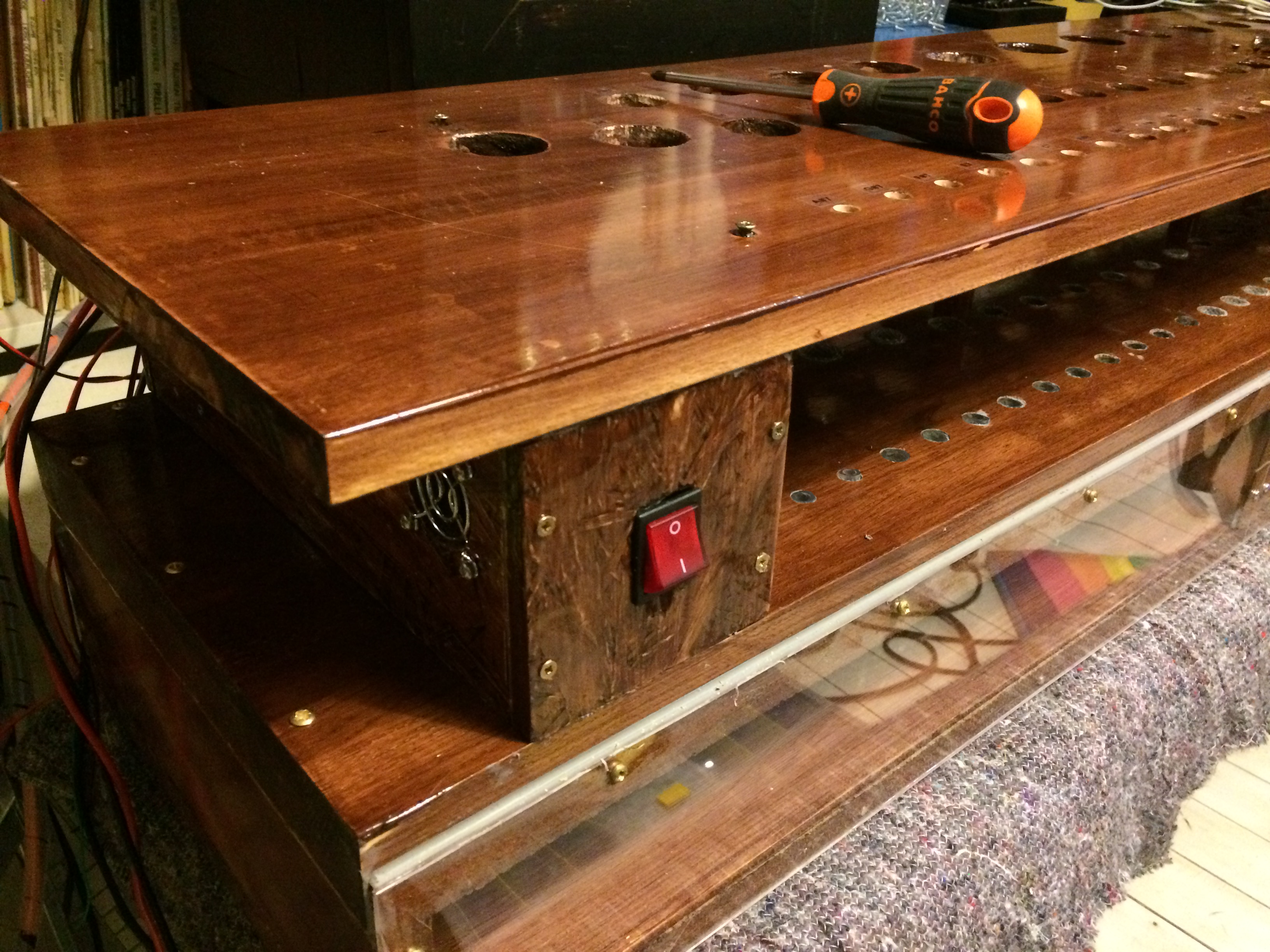
On the PipeDream61 toeboard we have much more wood thickness to work with, and combined with a varied selection of tube sizes we can hide the tubes completely in a 20 mm countersink. However, some of the larger pipes were quite damaged on arrival, and will need a better toe seal.
The image above shows the almost finished windchest, with rubber seals in the toe board and the raised pipe support board. Here you can also see our choice to make the front of the windchest transparent for effect. As seen in the video above, we also placed an orange LED on each solenoid valve, also for effect.
Between the toe board and support board we have a power supply for the organ, but more about that later.
THE PIPES
The pipes are a complete 4 ft diapason/prinzipal rank of lead/tin pipes, with the lowest octave being lieblich gedeckt. The range is C3 (130 Hz) to C8 (4186 Hz). Unlike the PipeDream24, this rank is actually one continuous and matched rank, and not a mix of different types and timbres, and so we’ll expect a much more uniform and balanced sound. Most of the pipes play perfectly well as they are, but especially some of the gedackts had a rough time being shipped from England, and they will need some special attention.
The highest octave pipes (C7-C8) are more or less unusable, as they emit very piercing, high-pitched sounds, almost like a choir of loud dog whistles. So, they are more for effect than music.
The age of the pipes is unknown, but the lead/tin has become very dark grey. It’s undecided if we’ll bother spending the time and effort needed to clean the pipes. As it has no effect on the sound, it’s all down to a balance between aesthetics and laziness.
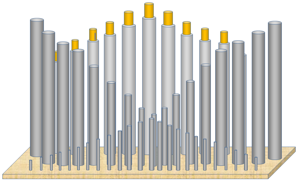
The pipe layout is more planned in the PipeDream61. This is an early visualization of the pipe layout, used in our planning.
LIMITATIONS OF A SINGLE RANK
Now, this is just a single rank, and so will not be able to sound like or even imitate the well-known diapason sound. In larger pipe organs the diapason sound is made of a compound mix of several pipe ranks in combination, so that one key on the manual actually activates several pipes at once, usually from about 4 pipes and up to maybe 8-10 pipes or even more. These parallel ranks – the partials or mutation stops – represent or boost the harmonic overtones in increasing pitch and decreasing volume:
- 1st partial: Fundamental/unison (the principal rank)
- 2nd partial: Octave (one octave above fundamental)
- 3rd partial: Quint, Twelfth or Nasard (one octave and a fifth above the fundamental)
- 4th partial: Super octave or Fifteenth (two octaves above the fundamental)
- 5th partial: Tierce, Terz or Seventeenth (two octaves and a third above fundamental)
- 6th partial: Super quint, Larigot or Nineteenth (two octaves and a fifth above fundamental)
- .. and so on
The graph below is a very simplified illustration of the first four partials. The Blue line is the fundamental/unison, the green line is the octave, the red line the quint/nazard and the pink line the super octave. The thick black line is the resulting combined tone curve, illustrating a much more complex and compound sound then any of the individual component sounds.

The tones are here represented by simple sinus tones, whereas actual pipes and ranks of partials will have a more complex tone curve, making the resulting effective tone even more complex and unique for each organ.
On a large organ the lower 4-5 partials can usually be added individually to the fundamental by pulling stop knobs, while the higher partials are grouped in so-called mixtures, adding several higher partials with a single stop control.
But all that is purely academic, as we don’t (currently) have any partial stops/ranks in EnsembleBot. In theory, one could imagine using the higher notes of the principal (fundamental) 61-note rank to play the higher partials using the same pipe rank. This is called borrowing, and is something that has been used to some extend to emulate a larger sounds in smaller organs, but it is also something that is harshly frowned upon. The real, dedicated partial ranks are voiced, tuned and attenuated to precisely compliment the fundamental rank, something that can never be achieved by borrowing within the same rank.
MOUNTING THE VALVES
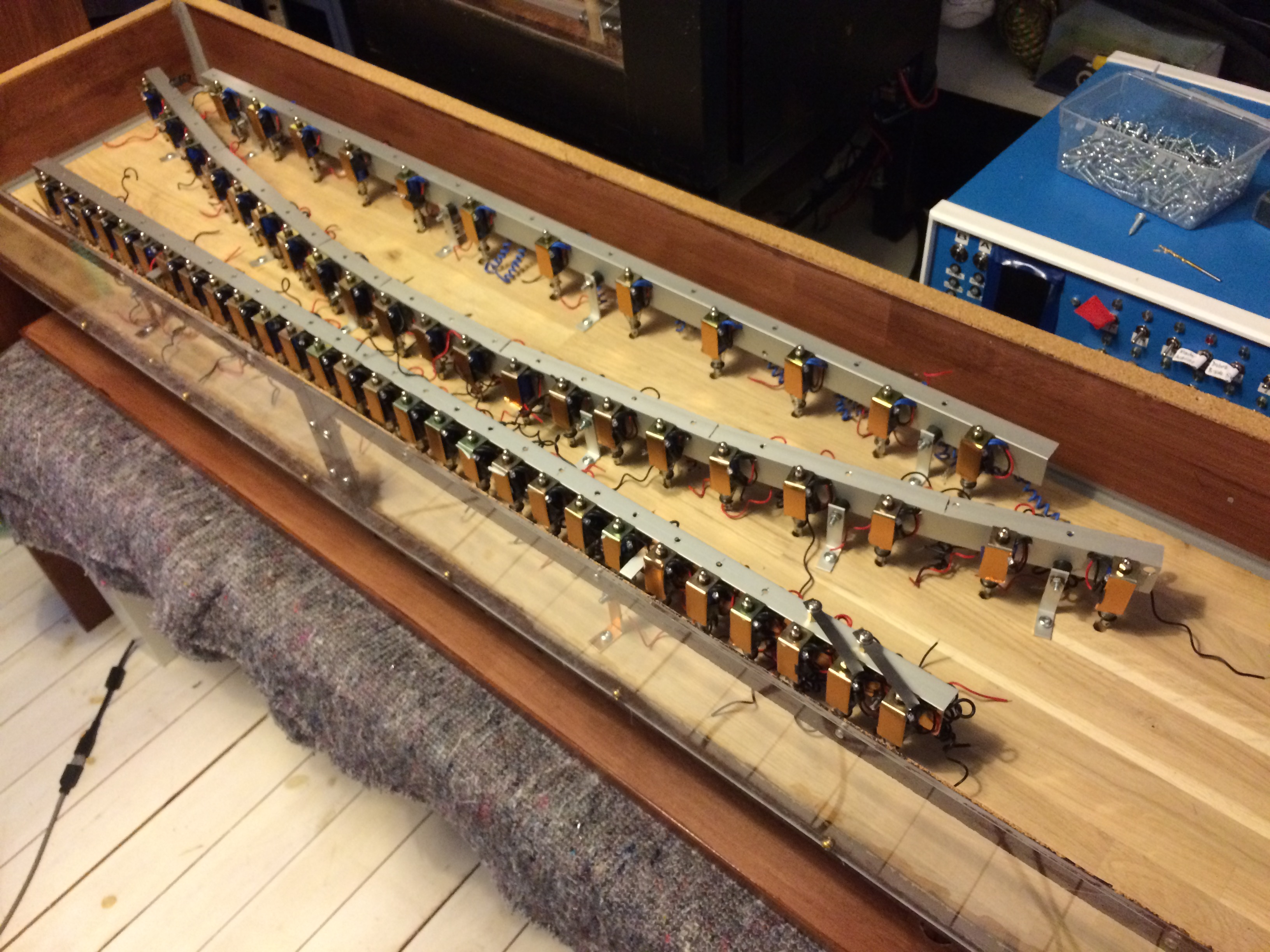
Here we see that the middle row of pipes is curved for visual effect. It is not exactly obvious, when you look at the finished organ, but it does give a bit of organic feel to the otherwise straight lines of the organ. And whether it’s noticed or not, we’ll know it – mainly because it was hell measuring the holes and making a curved mounting rail for all the valve solenoids.

Above is the windchest with all solenoid cabling finished. The thick white wires seem very prominent, but they are almost invisible when the windchest is closed and turned upside down, even though the front of the windchest is acrylic glass.
The cables are routed through 8 holes up through the toe-board to aviation connectors. These are the airtight connection between the organ controller box and the windchest.
We’ve added 3 extra valves on the backside. These are traditional magnetic organ valves, that we got after we passed the point of no return on our linear solenoid valves.
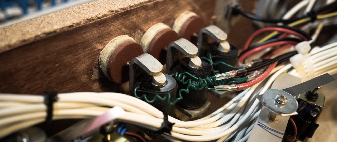
Even though we might not end up using all of them, it would be a shame to waste 3 good valve control ports (the rank only has 61 pibes, but the controller stack supports 64 valves). The original valve pallets have been replaced with a more airtight foam-rubber cushion and a new leathering. The air output on the back are 1/2″ brass male tube fittings.
So far we have a G2 (98 Hz) wooden gedackt from our test organ, that is a nice addition in the PipeDream61 rank. The other one or perhaps both ports will be used for our zimbelstern project.
ORGAN CONTROLLER
We use the same modular driver boards as the PipeDream24, though of course in the PipeDream61 we’ll have a full stack of 8 boards for 64 driver ports.
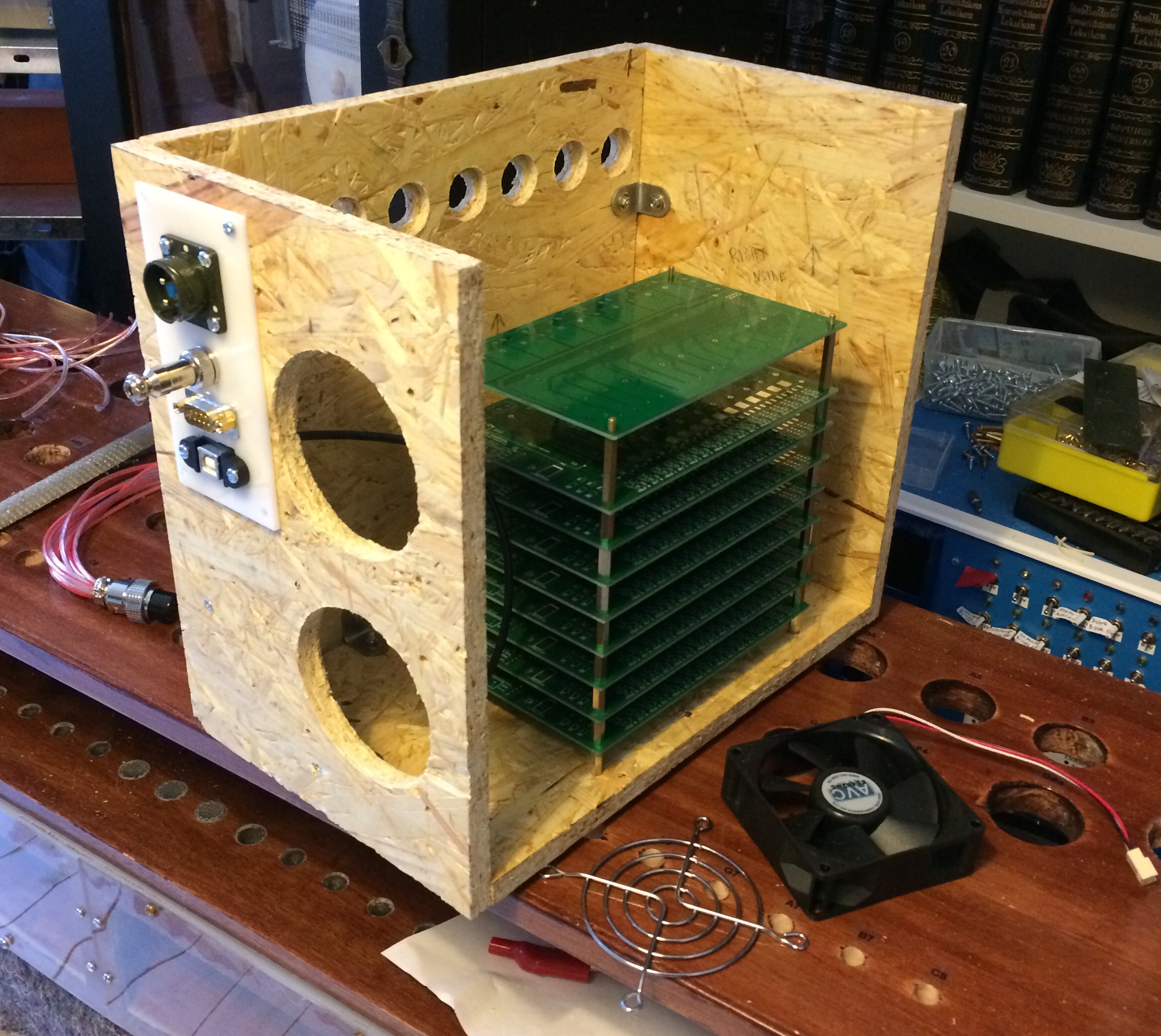
The controller and driver stack is placed in its own enclosure, mounted on the end of the windchest. The image shows the enclosure under construction. At the side facing the windchest we have 8 holes for cable glands for the wires to the solenoid valves. The backside has some cable connectors for power, CAN bus as well as a USB connection for re-programming or debugging the controller MCU. The two large holes are for the cooling fans. The front side will have a panel for display, buttons and so on.
But most prominently, the driver stack (at this point just bare PCBs) is shown in place.
PICKING A BRAIN
To manage the larger organ we chose to use a larger microcontroller than the Arduino Nano used in PipeDream24. Handling 61+ pipes as well as CAN bus communication and EBP parsing is pushing its limited SRAM (2KB) to the limit. We could have used a Mega with 8KB RAM though with the same 16MHz clock, but to be sure we had enough muscle, we ended up playing it really safe.

The choice was between an Arduino Due (84Mhz and 64+32KB RAM), a Teensy 3.2 (72MHz clock and 64KB RAM), or a STM32F103C8 a.k.a. Blue Pill (72Mhz and 20KB RAM). In the end we chose the Teensy, primarily because of its practical size and a bit better library support. It’s a 3.3V MCU, but that is no problem as the digital ports of Teensy 3.2 are 5V tolerant. The Teensy has native CAN bus, so we just needed a 3.3V CAN transceiver for communicating with the EnsembleBot Master. Read more about our choice of microcontrollers in our microcontroller page.
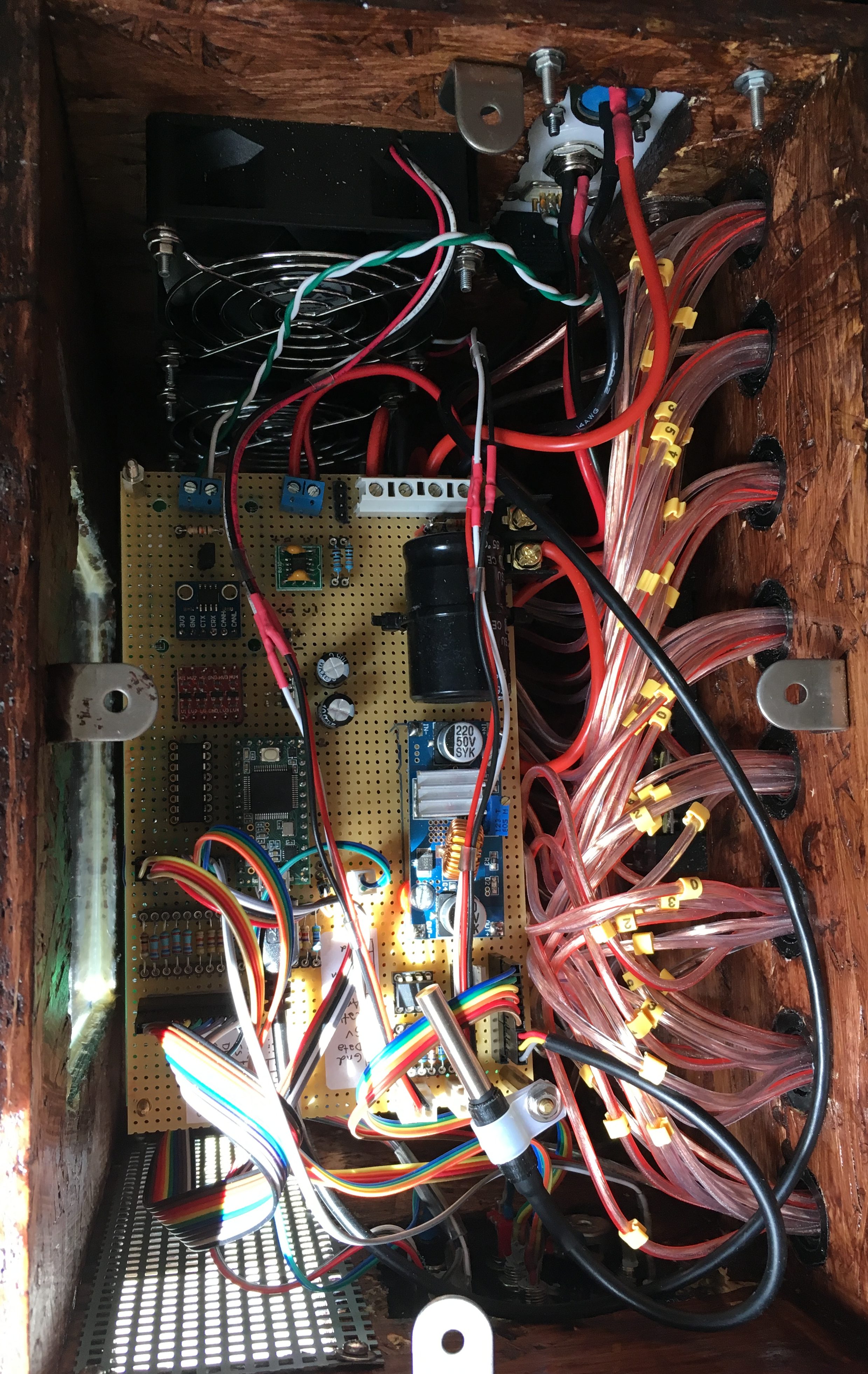
But, unlike the PipeDream24, the actual organ controller will not be burdened with measuring temperature and control cooling fans. Instead we have a separate controller (an ATtiny85, top right corner of the image) to handle temperature control inside the controller enclosure. The sensor is a Dallas DS18B20, and the microcontroller can activate/deactivate two 80 mm 12 V cooling fans through a MOSFET driver. This cooling circuit has an RGB LED as status feedback, and it’s placed on the B-side power domain.
The image to the right shows the finished controller enclosure with the top lid removed. It’s not exactly pretty, but it’s solid. Unfortunately it’s has proven to be a bit troublesome to access the driver boards. Because of all the cabling to the windchest valves, we need to attach and mount the driver boards one by one.
POWER SUPPLY

Most of the other slave instruments in EnsembleBot receive A-side and B-side power from the central power supply. In PipeDream61 we built a separate B-side 12 V power supply into the windchest. This makes it easier to physically place the much larger organ without having to run long high-current power cables from the master power supply. We just need some low-current A-side power and the CAN bus. In principle we could even supply the A-side current through the CAN cable (Cat-6 S/STP), but that shouldn’t be necessary.
The power supply is mounted between the toe board and the pipe support board.
WINDCHEST MONITOR
We’ve placed an independent monitoring system inside the windchest. This constantly monitors the air pressure inside the windchest, but will also monitor the state of the power supply unit.
PRESSURE
The classic way to check the windchest air pressure is to build a U-shaped manometer. We don’t want to involve too many liquids in our design, so we look for solutions elsewhere. We use a Bosch BMP280 barometric pressure sensor. These babies measure the barometric pressure, maybe not with the highest absolute precision, but with sufficiently high relative precision. What that means is that we make an initial measurement without windchest pressure (i.e. atmospheric pressure) to get a calibration benchmark (at power-on or on demand), and from then on we measure the relative pressure difference from that benchmark.
PSU TEMPERATURE
To monitor the power supply we measure the temperature and current levels. The temperature sensor will again be a simple Dallas DS18B20 OneWire sensor. They are easy to work with and are pretty reliable.

POWER USAGE
To monitor current usage we’ll use an INA219 high-side DC current sensor with I²C interface. We’ve used this chip extensively in our EnsembleBot power supply, and they are really a pleasure to work with. We use the sensor to ensure that the current drain does not exceed a predefined limit. To measure up to 16 A, we remove the 0.1 Ω shunt resistor built-in to the INA219 beakout modules. Instead we place a 0.020 Ω shunt inside the PSU enclosure and connected lead wires to the two shunt poles into the windchest with the INA219. That way we keep the shunt close to the PSU and the sensor close to the monitor MCU.
If something should happen to make the organ controller firmware stall/freeze with valves fully open drawing 10+ amps, we would like to have a safety to prevent physical damage to the components. So to be able to act on the current measurements, we also need a relay to cut the power to the controller. A standard Songle 30 A relay should do it. Controlled by the monitor MCU, this relay cuts the 12 V main power line to the organ controller/driver stack, while maintaining power to the monitor circuit.
FEEDBACK
Finally, we want some kind of feedback on the organ status. We would have liked some nice feedback on air pressure using a graphical representation of the pressure and PSU current history, but found that our graphical LCD/TFT displays were too slow and/or use too much of the microcontroller’s limited ressources. So, instead we settled for a simple 20 × 4 LCD text display combined with three RGB LEDs.
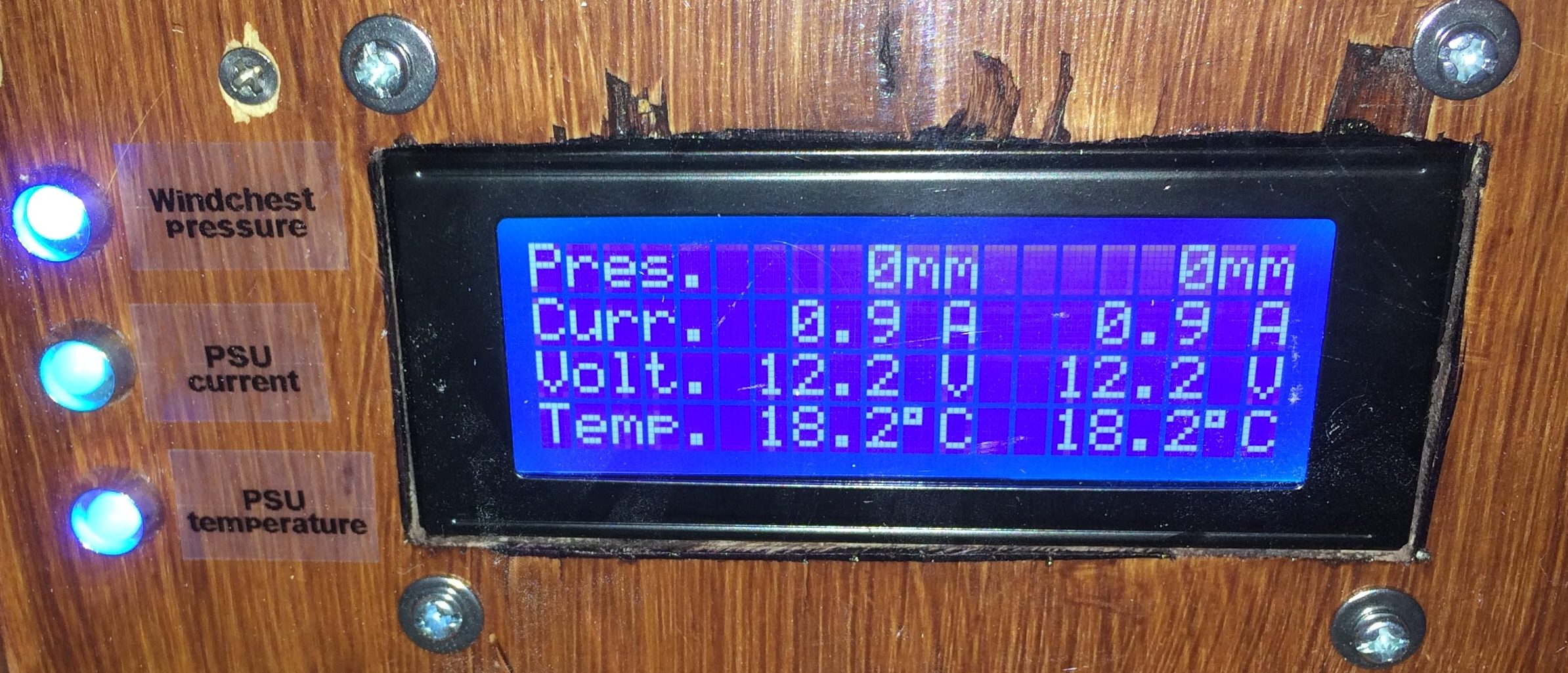
The display shows slowly updating mean and extreme values of air pressure, current, voltage levels and PSU temperature. The three RGB LEDs show constantly updated feedback on pressure, current and temperature.
Next: Read about the Zimbelstern project
Hi there! I just stumbled upon your website, and are fascinated by your works. How can i get in touch with you guys? I’m from copenhagen and have just started on a organbuilding project and would love to ask you some questions, but cant find any contact info on your website.