The EnsembleBot is growing bigger, and we need to address some issues with supplying power for especially the A-side components (i.e. microprocessors and communication).
The slave instruments are connected to the master circuitry via a CAN bus, while the A-side power (and sometimes the B-side power as well) is supplied directly from the central power supply. This makes it quite annoying to run cables between instruments, especially if we want to use a more flexible and ad hoc bus topology.
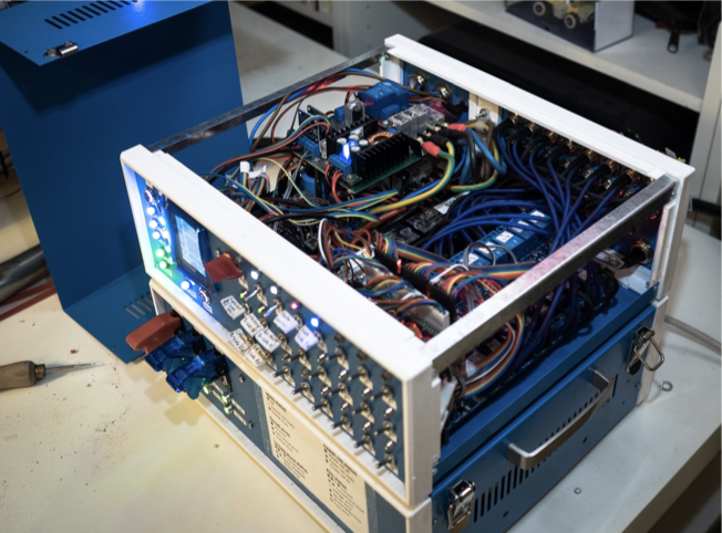
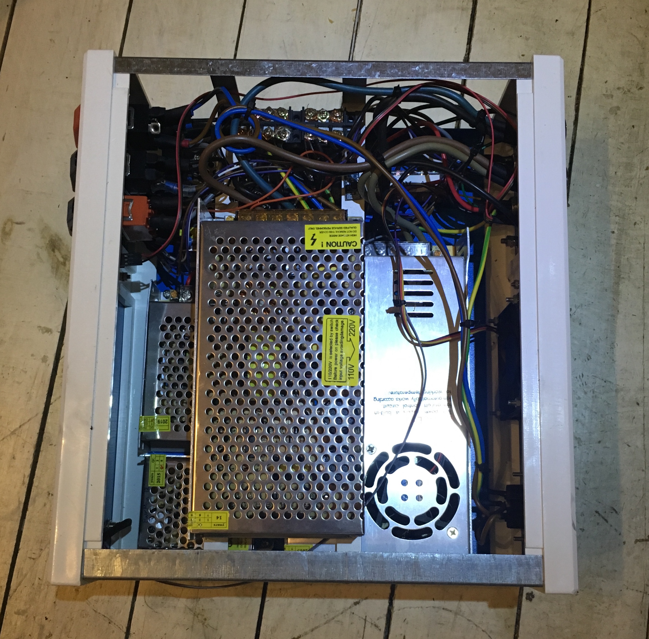
Inside the bottom PSU enclosure
So, we are going to run a common A-side 12V power line along the CAN bus cable to cover all A-side power needs. If a slave instrument needs A-side 5V, it must use the 12V line and step down the voltage locally.
Until now, we only had a small 12V/2A PSU for the A-side. To support a wider use of this power line, we have replaced it with a more powerful 12V/5A PSU. Fortunately, this could be done with only minor physical alterations to the central PSU enclosure, and a very minor update to the central power supply monitor firmware.
16-channel MOSFET drivers for electromagnet organ valves
Damn. After assembling and air soldering the last two pipe driver boards for the PipeMare controller circuitry, I realized that I placed all the onboard LEDs the wrong way. So now, there are no fancy lights to indicate that the board is functioning correctly.
Furthermore, it turns out that the 12mm brass stand-offs that I planned to use to stack the boards (like the PipeDream organ drivers) are just one millimeter too long for the entire stack to fit into the PipeMare controller drawer. If I had a small lathe, I could easily have shaven off a bit of the 12mm stand-offs, but lacking the right tools I have to order them from China. No big deal, but still yet another delay.
The controller in the PipeMare triple-organ must handle communication with the master, monitor the local power supplies, and of course manage and play all three instruments in the PipeMare cabinet. This means that the controller circuit will be a bit more complex than in the other EnsembleBot instruments.
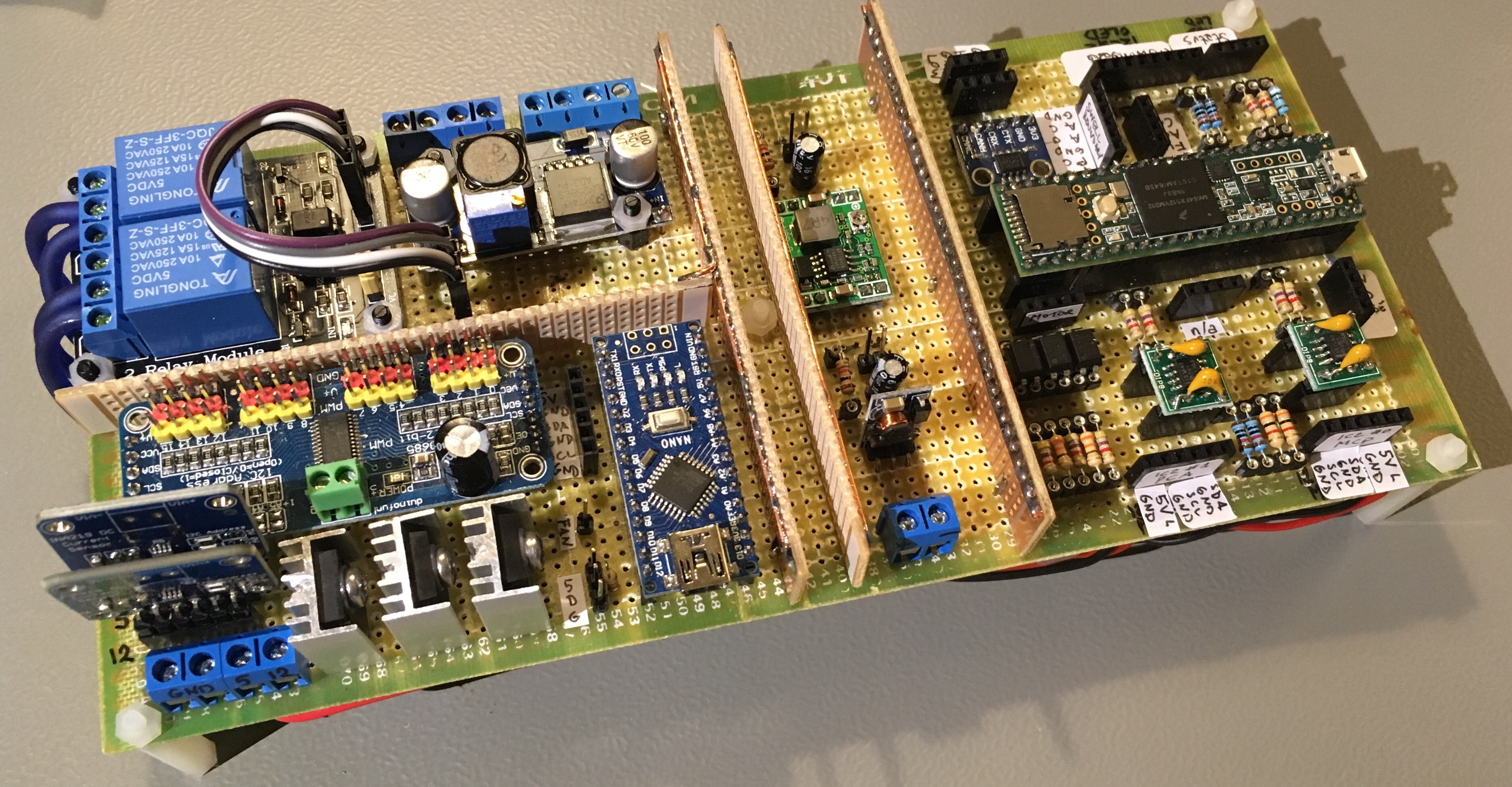
The PipeMare controller assembled
The board is divided into sections by some vertical ground planes to reduce noise from the on-board switching step-down converters. The right side is the main A-side circuitry with the Teensy 3.5 microcontroller in the center, a CAN-bus transceiver, two I2C isolators, optocouplers etc. Just to the left of the main circuitry are two small switching step-down (buck) converters to make stable 5V and 3.3V out of the 12V from the master power supply.
The left side holds the B-side circuitry. In the top left corner is a dual relay for the 5V and 12V power lines, and next to it a step-down buck converter to make a stable and relatively noise-free 5V supply for the secondary controller and support circuitry.
In the bottom left corner we have the secondary controller (Arduino Nano), a PCA9685 PWM-driver board for status RGB LEDs, as well as two INA219 high-side current sensors and their shunt-resistors. This controller will also be connected to one or more Dallas DS18B20 temperature sensors, and to the optocouplers facilitating the simple status messages between the A-side and the B-side controllers.
The controller board is completely cabled, but nothing has been tested yet.
The two pipe windchests inside the PipeMare cabinet are now finally installed. It looks great, and fortunately they fit perfectly.
Both pipe windchests installed
We’re still quite a long way away from having a working instrument, though. Besides general debugging, tweeking, voicing and tuning of the pipes, we haven’t yet built the control and driver circuits.
We also need to finish the PipeWind pressure monitor and evaluate the pressure responses in the wind system.
Finally, the PipeMare Flute windchest is (almost) finished. It has been thoroughly pressure tested and the wooden pipes has been mounted. Here it is, placed up-side down (when mounted inside the PipeMare cabinet, the pipes will be hanging down from the windchest):
The PipeMare Flute windchest finished
I’ve done nothing to make the windchest look good, because it will be completely hidden when mounted inside the cabinet.
There are some minor issues with a few of the pipes and/or valves that need to be solved, but that is not a problem. A more serious problem is that several of the pipes are overblowing at the 3″ w.c. test pressure. This is not surprising, as they are from an organ with a 2″ w.c. pressure. So, now we need to find a way to deal with this.
There are basically three options:
We can try to restrict the air pathways to the overblowing pipes as a way to reduce the effective pressure and flow to the pipe. This is a very low-tech solution, but might result in unbalanced volume levels from pipe to pipe.
We can build a secondary pressure regulator between the PipeWind manifold to reduce the main 3″ pressure to a 2″ pressure specifically for the Flute rank. This is clearly the most complicated solution. It could be fun to build, but would introduce another significant delay to an already severely delayed project.
The third option is actually absurdly simple: Reduce the organ main pressure. Both the PipeDream61 pipes (designed for 3″ w.c.) and the PipeMare Accordion can easily work on a lower pressure, like 2.5″, but there might be a problem with the PipeMare harmonic piccolos. These pipes are indeed designed to overblow on purpose to sound an octave above normal, helped by the small puncture at the middle of the pipe tube. So, we’ll have to do some more precise tests of both the piccolo and flute windchests to see, if there is a sweet spot, where both pipe ranks speak nicely.
We’ll try out option 3, and if that doesn’t work out, we’ll consider options 1 and 2.
One step forward, and two steps back. My office day job has given me lateral epicondylitis (tennis elbow), so work has slowed down even more. Fortunately, many of the immediate tasks are not too physically demanding.
I’ve used some time checking/repairing all magnet valves and wiring up the PipeDream Flute windchest. However, the windchest failed the first pressure tests. The leather pallet surfaces of the magnet valves are just too old and stiff and do not make a good seal. I will probably have to replace the pallet seal surfaces with a softer leather. Under normal circumstances, this wouldn’t be a problem, but since the valves has already been installed and wired together inside the windchest, it becomes quite a bit more difficult. Sigh.
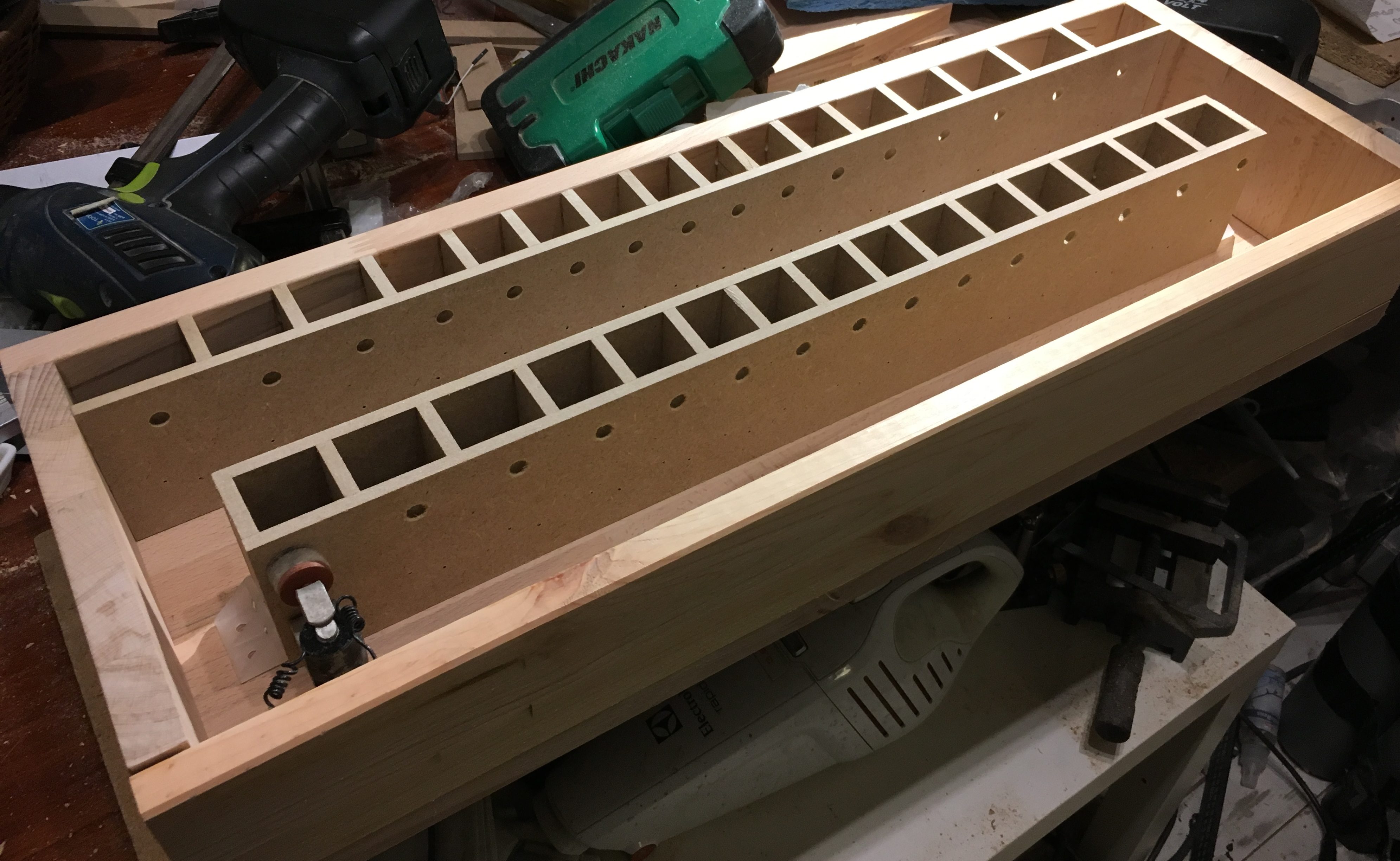
Finally some progress. The windchest for the PipeMare Flutes is well under way, and as mentioned in an earlier update, we have changed the basic design a bit, compared to our other windchests.
PipeMare Flute windchest under construction
Instead of placing the magnet valves directly under the pipes, we let the valves vent into a small expansion chamber and from there into the pipe. Hopefully this small buffer will improve the attack of the pipes. If not, well, then at least it was fun designing and building (and fortunately quite easy and cheap).
PipeMare Flute windchest under construction
There is still a lot of work before the winchest is finished, but most of the actual construction is done. We only need to make the expansion chambers tightly sealed, drill holes for the air intake and the electrics and drill out the exhaust holes for the pipes. Then, of course, there is the mounting and cabling of magnet valves, but that is trivial.
While struggling to make progress in the PipeMare project, we also work on expanding our selection of basic percussion instruments. We are currently experimenting with some kind of bass drum effect – without an actual bass drum. The plan is to use a cheap bodhrán and one or two modified bass drum pedals.
Instead of a foot stomping on the pedal, we are going to use some kind of heavy-duty actuator. Our first idea was to use the kind of bi-directional linear actuators used in car locks. These are very easy to control electrically and apply mechanically, and they are very strong. But they do have a serious flaw: Overheating. A bass drum is expected to be able to beat several times per second over a longer period of time, and that is a bit too much for the internal motor and gearing of a car lock actuator.
So, instead we turn to our usual fall-back plan: solenoids! The linear solenoids we’ve used so far, are not strong enough to pull a bass drum pedal, so we have to take it to the next level.
12V 45N solenoid
Here is our primary candidate, compared to one of the solenoids used in our glockenspiel. It’s a 12 V solenoid, with a stroke force of 45 Newton (or appx. 4.5 kg) and a 15 mm stroke length. It looks and feels like it could easily tear apart the entire EnsembleBot. It should be strong enough to pull the bass drum pedal with sufficient force, and it won’t overheat. Our greatest concern is how the power supply is going to react to the sudden sinking of 2.5 A on the 12 V line. Some huge capacitors across the MOSFET driver might be a good idea.
Speaking of MOSFETs, most of our older homemade driver modules used more generic MOSFETs like IRF520 or IRF530. While they open up sufficiently for the smaller solenoids, they’ve driven so far, we’d like to be sure, that they are fully open (i.e. lowest resistance) to drive these large solenoids. So, we’ll have to either replace them with logic-level MOSFETs (e.g. IRL540) or (perhaps easier) just build a new MOSFET array module.
We are also going to finish our dual woodblock, to be mounted inside the main cabinet with the tubular bells and the snare drum. The components and the mechanics will be very similar to the snare drum, so there’s really no excuse for the delay.
Things are moving a bit slow these days. Some profound thought about the PipeMare cupboard swell has resulted in a few design changes. The rather thin and flimsy backside will be replaced by heavy particle board, the edges of the front door will be sealed better and the swell panels will be reinforced to achieve better thickness/weight and a better seal. All this to make the effect of the swell as powerful as possible. With thin walls and bad seals, the swell effect would be almost unnoticable.
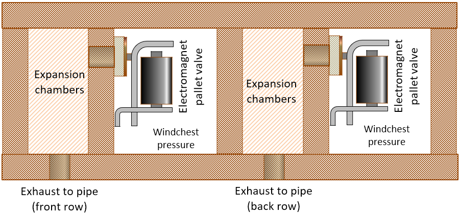
The PipeMare Flute windchest has also undergone some design changes. We are now working on constructing the windchest with built-in expansion chambers for the valves to reduce the stuttering onset or attack of sound, that might be the result of too short a pathway from valve to pipe. This is especially relevant here, as we have reduced the pipe feet greatly by removing their original long lead feet.
Here are some preliminary design sketches:
Windchest design proposal for flutes
Note that the flute windchest will be placed at the top of the inside of the cupboard, and the flute pipes are hanging upside down. That’s why the exhausts are pointing downwards.
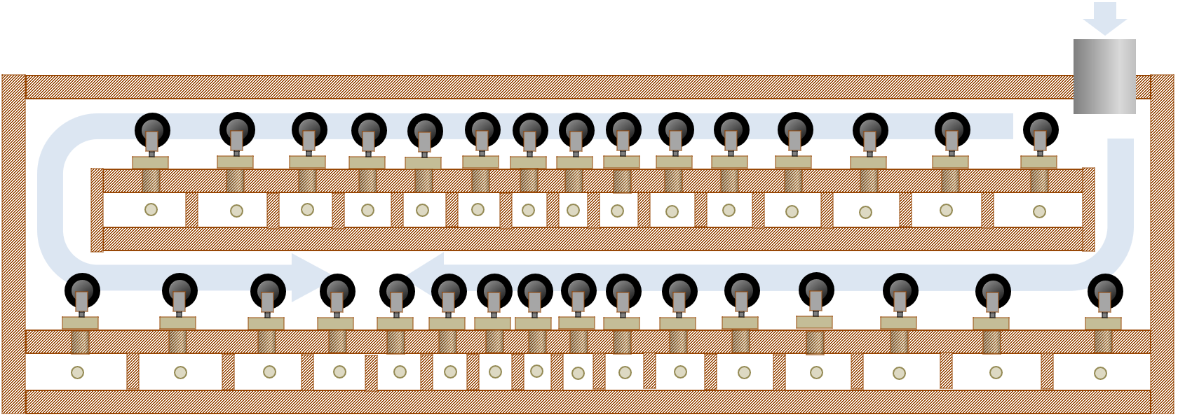
Flute windchest with expansion chambers – top view
The sketches are not to scale, and may be subject to many changes in the time to come. But having ignored the value of expansion chambers so far, we are very keen on using them at last, because they should be part of any respectable organ, and we do so desire respect.
Next, I expect we’ll have to build a tracker action pallet/slider chest…
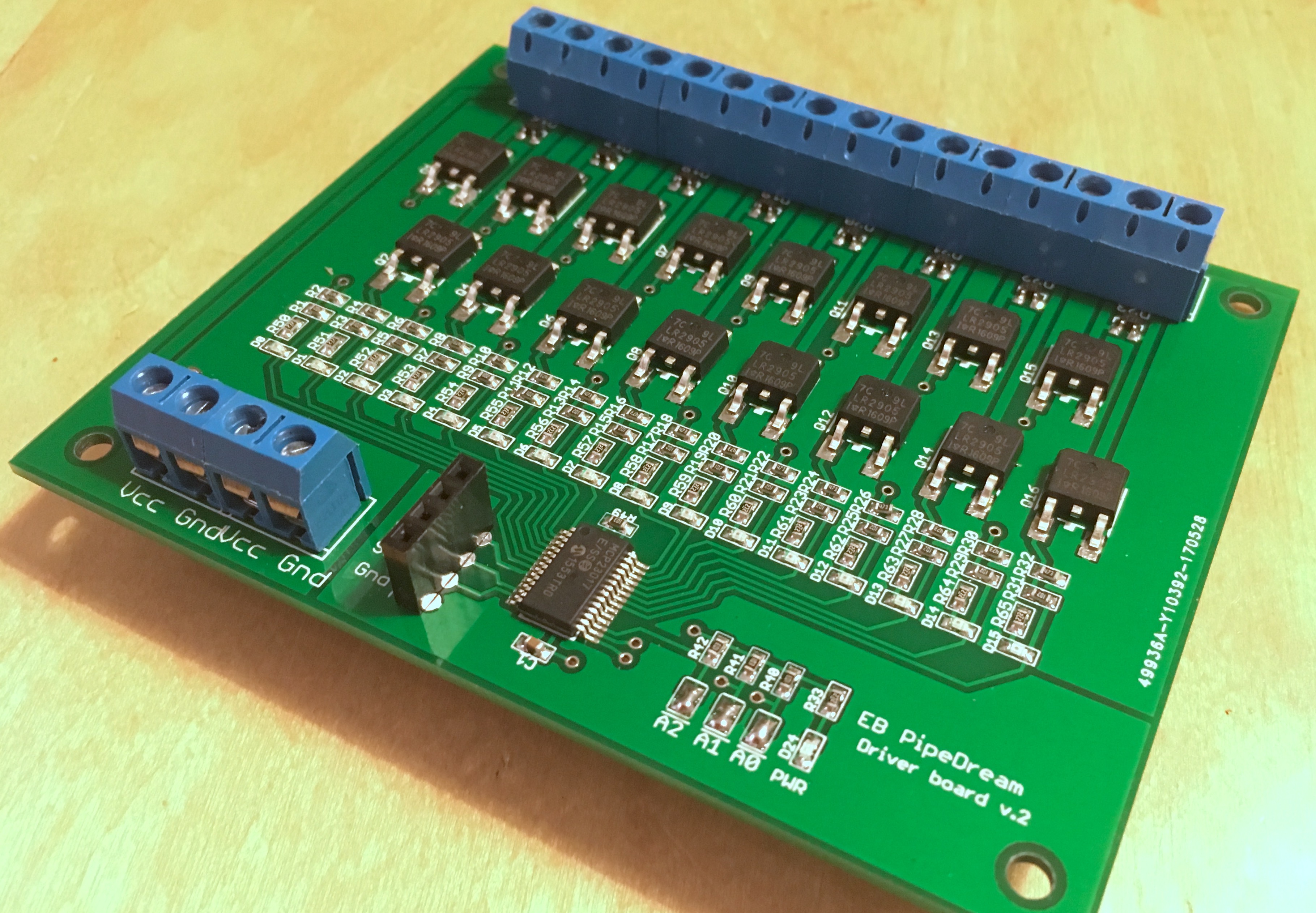
It has been more than a year since I designed the new magnetic valve driver boards for the PipeMarepiccolo and flute ranks and had them manufactured in China. Even so, I never tested them until now. As the piccolo windchest is complete, the only way to properly test it is with a driver stack, so now is the time to begin assembling the driver boards. Here is the very first assembled board:
The first of the new stackable 16-channel valve driver boards assembled
Fortunately, the board works just fine. Of course, it’s a bitch to air-solder all those SMT components by hand, especially the tight-pitched MCP23017 E/SS (SSOP package). But also fun, and it looks great.
On the other hand, the modified library I made for the drivers to accomodate microcontrollers with multiple I²C busses (like the Teensy 3.5) did not work. This is most likely because I suck at C programming and don’t really know how to use pointers and references. Well, I guess I’ll have to learn.