June 8, 2022: (Slow) progress

EnsembleBot is not dead! It just smells funny. Progress has been rather slow, but some progress has been made, nevertheless.

FIRMWARE

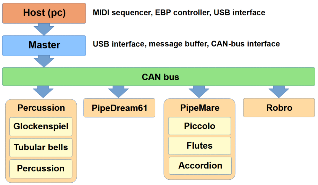
There has been a lot of firmware re-coding of the instrument controllers. The CAN bus handling and the local bus buffering has been streamlined. This should make the firmware code across the EnsembleBot more homogenous, as well as preventing the nasty bottlenecks and buffer overflows, that used to plague the busses.

UPGRADED PERCUSSION CONTROLLER

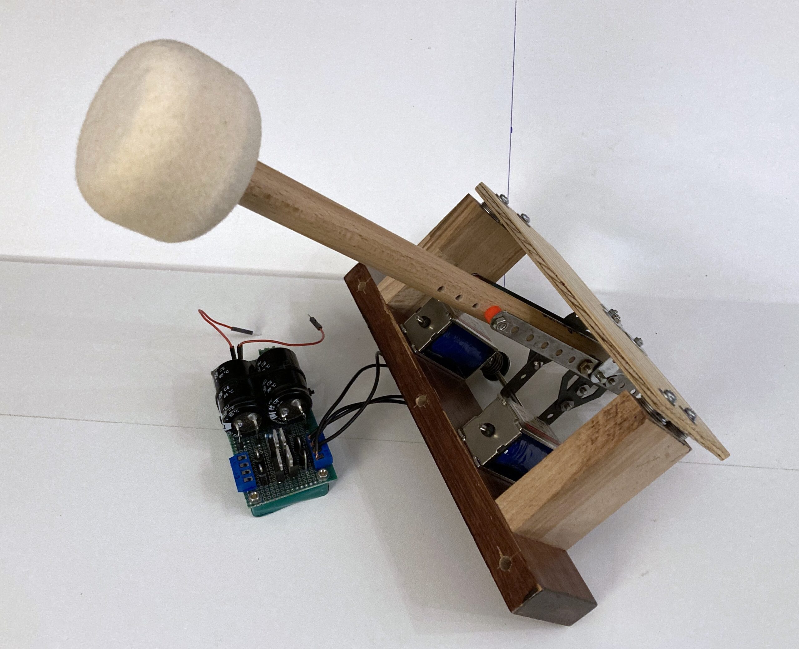
The percussion controller manages both the tubular bells, glockenspiel and the miscellaneous percussion. In some music pieces, this instrument group can be very busy indeed, so to make sure we don’t exhaust the buffers and limited CPU time, we decided to upgrade the Arduino Mega (8-bit, 16MHz) controller to the almost pin-compatible but much more powerful Arduino Due (32-bit, 84 MHz ARM).

Now, while the Due is almost identical to the Mega regarding form factor and pin configuration, there are some important differences. Obviously, the Due is a strictly 3.3 V MCU, while the Mega is 5 V. Fortunately this poses no problems in our setup, which can easily work at 3.3 V levels.

But because I didn’t pay attention to the specifications of the Due, I didn’t realize that it hasn’t got an onboard EEPROM, like pretty much all other MCU development kits. Why is this a problem? I’ll come back to that in a moment.

On the plus side, besides more CPU power and SRAM, the Due boasts two I2C busses and an embedded CAN bus controller. Both of these features are of interest to us. The CAN controller allows us to use the good old SN65HVD230 3.3 V CAN transceiver, that we use in all the other parts of the EnsembleBot, and the CAN bus library for Due is much better than the old one, we used in the Mega.
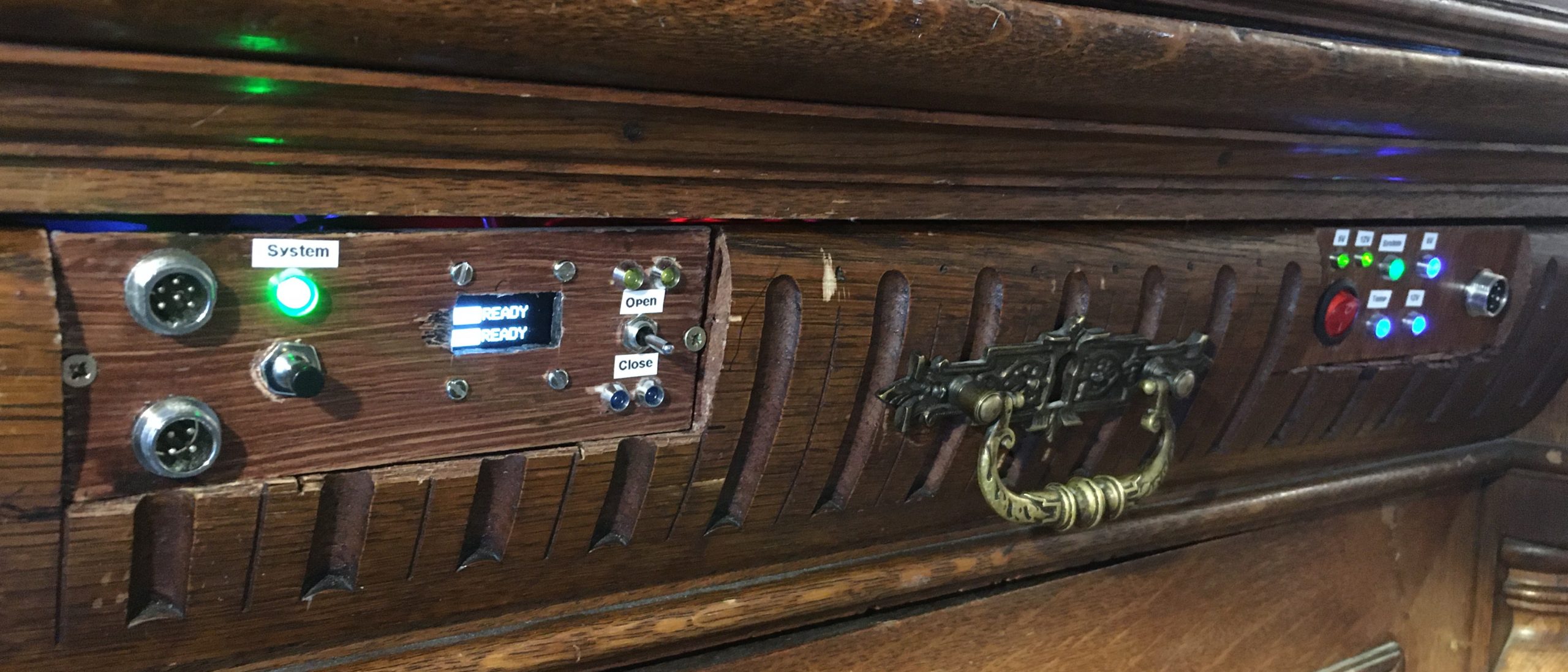
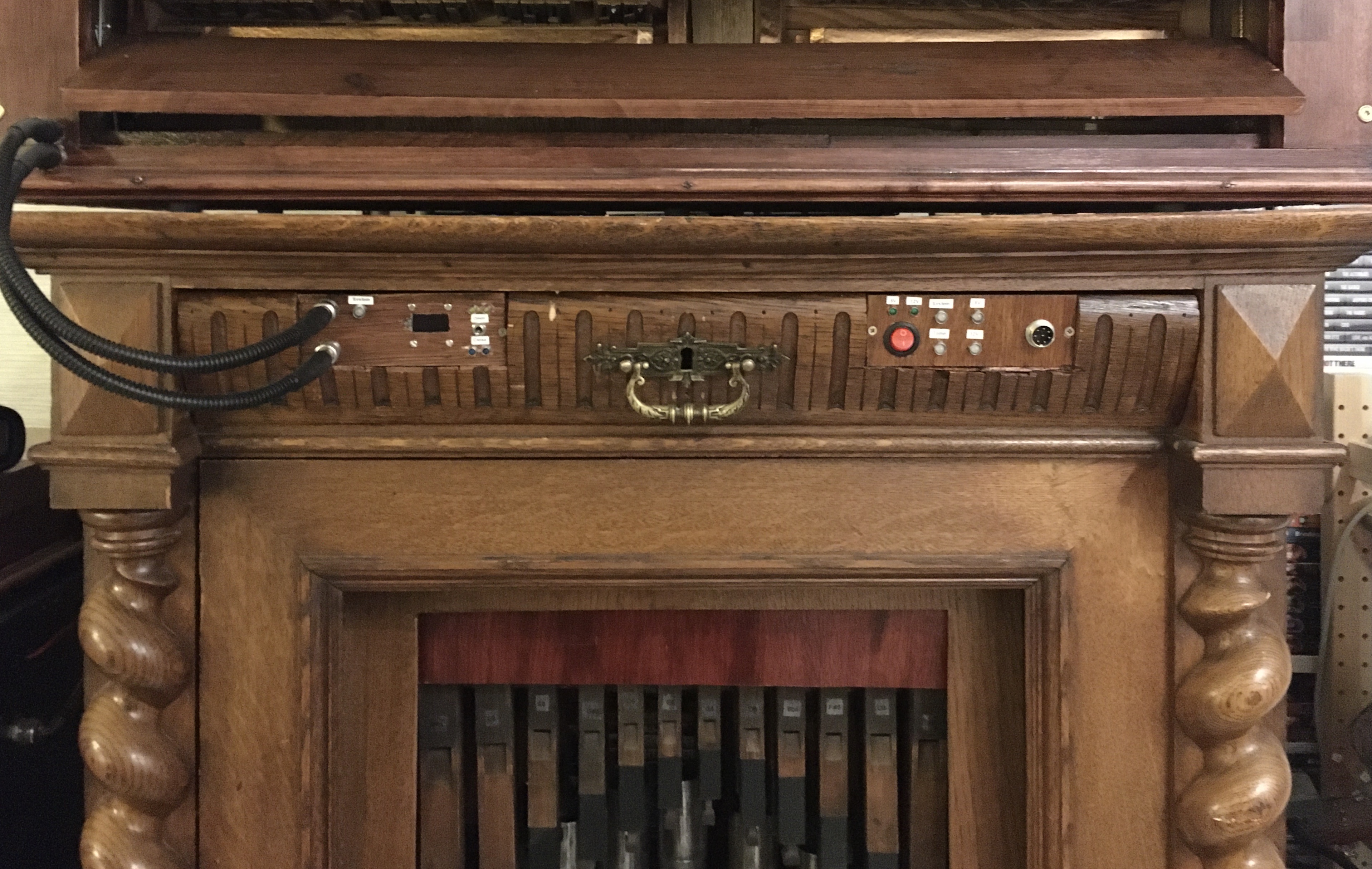
BUILT-IN CALIBRATOR

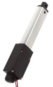
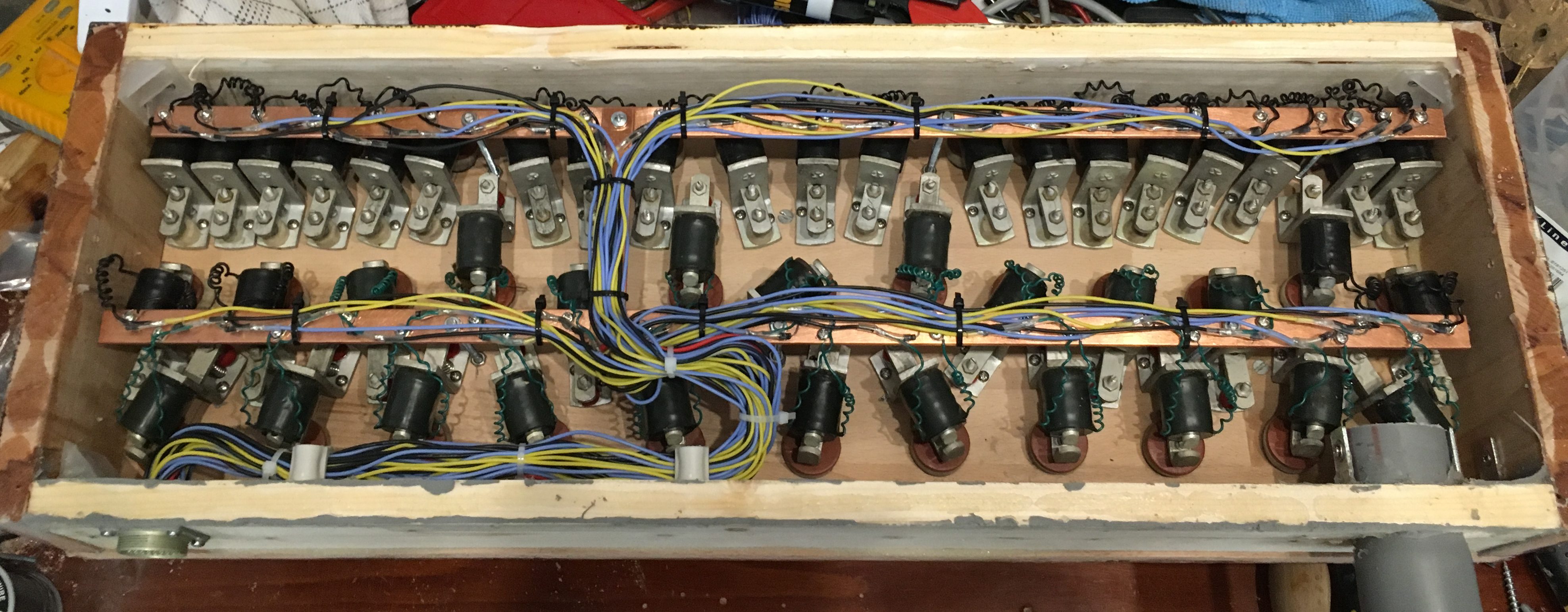
While we are upgrading the hardware and the firmware of the instrument controller, we also enabled the use of MIDI velocity on all the percussive instruments to give some dynamic range to the instruments. All the instruments are based on linear solenoids, so it’s rather limited how much dynamic control we have, but some is better than nothing.

The only way to control the dynamics (or “volume”) of the bells and drums etc. is to adjust the actuation time of each solenoid. A short actuation means a softer stroke, and a longer actuation means a more powerful and louder stroke.

Each solenoid must be individually calibrated to determine it’s particular minimum and maximum actuation times. And what’s more, the calibration changes over time. Given that we currently use more than 50 solenoids, and more might be coming, it could easily become a quite annoying task to determine the calibration values, hardcode them into the firmware, upload the firmware and test. Repeat ad nauseam.

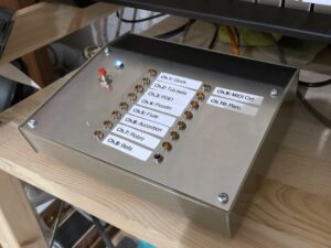
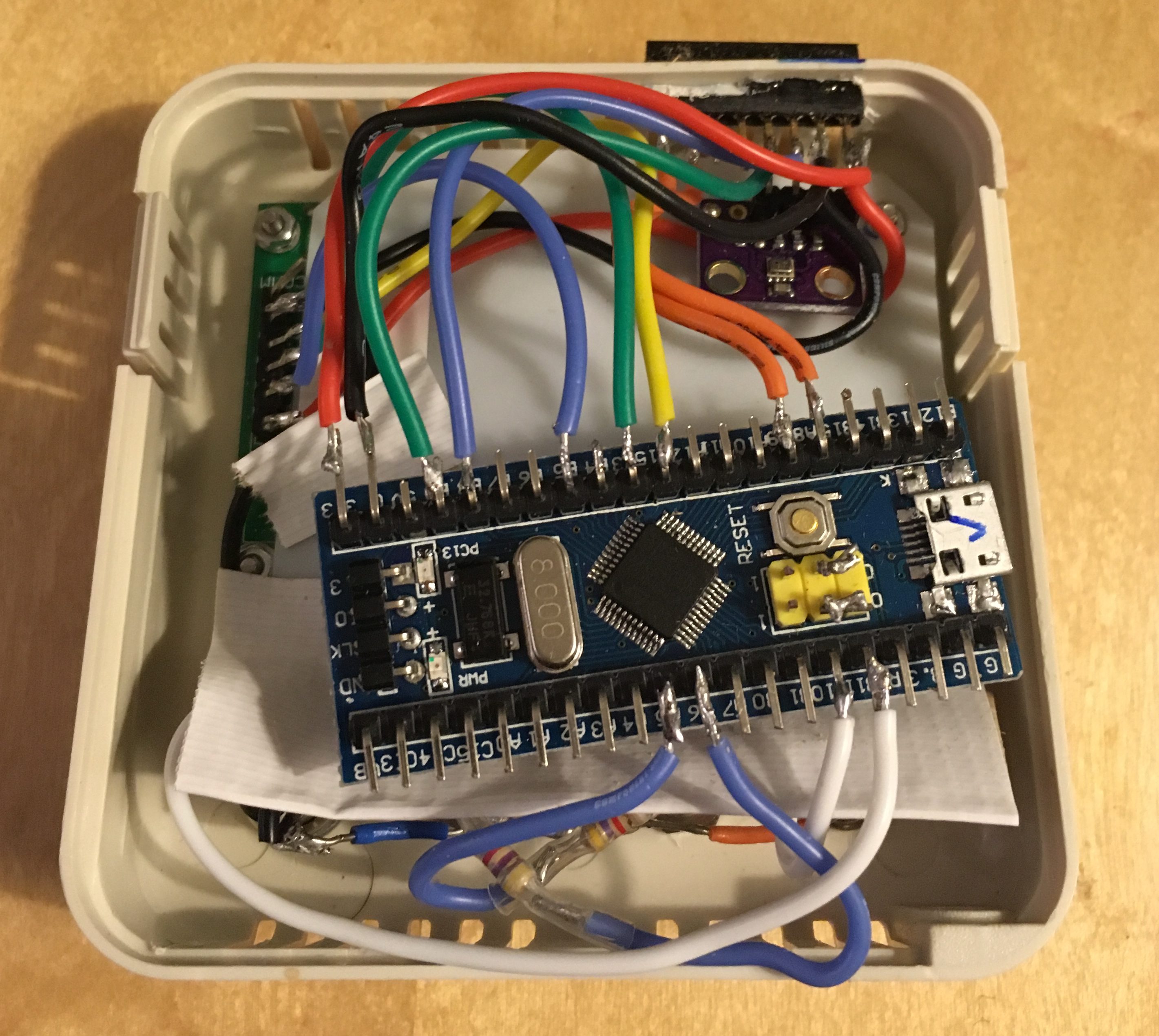
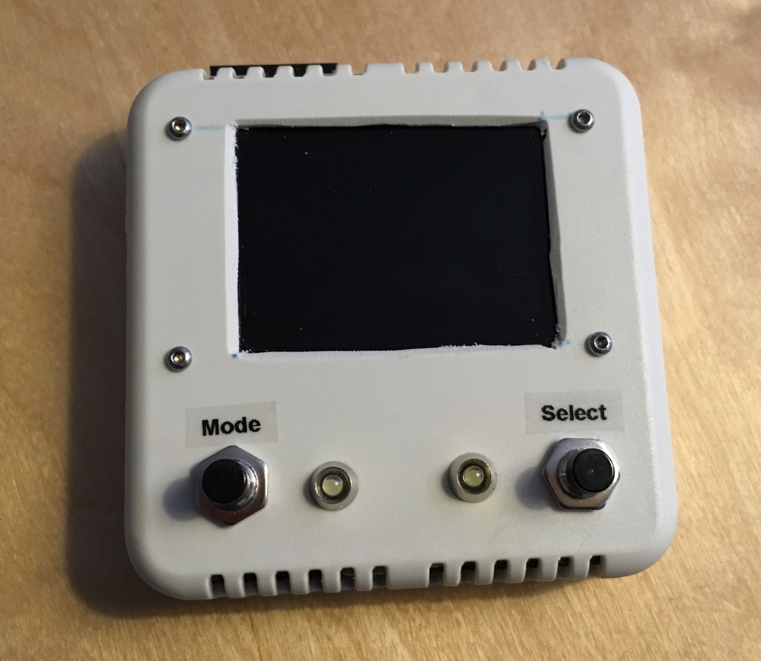
So, to make this task easier, we built a dedicated calibration circuitry. This consists of a small OLED display, 4 pushbuttons and an I2C EEPROM module (because the Due hasn’t got one, but it does have a secondary I2C bus which we can now dedicate to the EEPROM module and OLED display). During MCU boot-up, one can enter the calibration mode, browse through the registered solenoids, change the minimum and maximum values and test them on the spot. All changed values are saved to the EEPROM, containing all current calibration values.

What would have taken me days to do before, can now be done in less than half an hour, and with no need for firmware changes or even the use of a computer.

January 12, 2022: Progress

Not many updates lately, but work hasn’t stopped entirely. There is still a very long way to go before the EnsembleBot can play, but we’ll get there, eventually.

DEDICATED MASTER CONTROLLER

The master controller is the bridge between the MIDI host (pc) and the EnsembleBot, and it’s main function is to relay MIDI/EBP messages from the USB serial bus to the EnsembleBot CAN bus. Previously, this function was served by the same microcontroller responsible for tubular bells, glockenspiel and miscelleaneaous percussion.

Master Controller Enclosure

To reduce the risk of buffer overflows because of too slow buffer handling (which actually did occur) the bus bridge tasks has now been moved to a dedicated master controller, that pretty much only buffers incoming serial messages and relays them onto the CAN bus.

Making a stand-alone master controller also helps keep the EnsembleBot more modular. Previously, nothing worked if the combined tubular bells/glockenspiel/percussion circuitry wasn’t present and switched on. Now, it’s possible to use only a single instrument (or instrument group) independently.

The master controller is based on a Teensy 3.2 (72 MHz). This is a bit oversized, but it’s better to err on the side of caution. This extra muscle makes the firmware coding easier, as it doesn’t have to be perfectly optimized. Also, to have some kind of practical feedback, the controller box has been fitted with 16 LEDs – one for each MIDI channel – that will light up shortly, when a MIDI/EBP message is sent to that particular channel.

The hardware is assembled and tested, but the firmware has yet to be written.

PIPEMARE SWELL PANELS
Linear Actuator

After many failed attempts, the PipeMare swell panels for both the accordion and the cabinet are now working. Originally, the swells would be controlled by silent, geared motors, combined with a number of micro-switches to check for extreme positions. Especially in the accordion it was very hard to make it work reliably because of space constraints.

To make a functioning swell panel, the geared motors were dropped for now in favour of much simpler linear actuators. These are 12V devices that extends or retracts a small arm in a slow and smooth motion, and they are able to exert quite a force. Another bonus is that there is no need for switches to check for extreme positions, as the actuator automatically shuts down, when it reaches the fully extended or retracted position. All that’s needed is 5 seconds of power, and the actuator takes care of the rest.

PipeMare swell doors

Unfortunately, these actuators are anything but silent. To be honest, they are quite noisy. This is a problem, since the swells were supposed to be part of the PipeMare instrument, changing the dynamics (volume) of the music through MIDI commands. However, as they are now, they would pretty much ruin any music playing when activated. So, unless there is some way to reduce the noise, they should be considered a temporary solution.

BASS DRUM
12V 45N solenoid

The percussion section really lacks a decent bass drum. Earlier attempts were underwhelming to say the least, so they had to be redesigned from scratch. After watching a youtube video of a MIDI-controlled drumbot, I contacted the creator, who gave me the inspiration for the next design.

First of all, the new bass drum will based on a large floor tom to give a more substantial sound. The previous two flimsy mallets are replaced by a single, heavy bass drum mallet. For activating the mallet with enough force, we use not one but two heavy duty solenoids in parallel.

Bass drum prototype

These two solenoids each pull 45 N (nominally) when actuated with 12V. In this application they will only be actuated very intermittently, e.g. 30 msec with much longer pauses in between, and the risk of overheating the solenoid coils is greatly reduced. So, to give the mallet extra force, the solenoids are driven at 15 V (i.e. a 25 % overvoltage) through a pair of power MOSFET drivers and a dedicated switching PSU block.

This, combined with a much more rigid and lossless mechanical mounting, gives the bass drum its much needed oomph. Now it’s just a matter of making the beater-system look good, and mounting it on the tom, along with the driver circuit and PSU block.

WHAT NOW?

Right now, the primary concern is firmware programming. The master controller needs new code, and the previous multi-purpose controller must be re-programmed to only act as slave-controller for tubular bells, glockenspiel and percussion.

Then there’s still a lot of work on the PipeMare project. The two pipe organ stops must be voiced and tuned, and perhaps it’s even necessary to build a secondary pressure regulator, if the flutes can’t work with the high pressure for the harmonic piccolos. And the accordion also needs some work, especially building and programming a handheld unit for calibrating the many servos and storing the information on EEPROM built into the accordion control circuit.

May 11, 2021: General update

Being forced to work from home during the pandemic means that practically all physical work on EnsembleBot has been stalled for more than a year now. This is quite annoying, especially since I compensate by thinking up new projects and enhancements.

Dedicated master controller

Currently, an Arduino Mega serves as both interface to the host and master controller, while also serving as instrument controller for the tubular bells, glockenspiel and misc. percussion. As the number of instruments in EnsembleBot grows, we’ve begun experiencing some data congestion problems. This is partly because of bad programming (i.e. not enough focus on bus priority and input buffering), and partly because of the current master controller, that quickly becomes a data bottleneck.

For these reasons alone it’s obviously a good idea to implement some separation of functionality by building a dedicated master controller unit. This actually makes the overall architecture of the EnsembleBot simpler and more compliant with the master/slave principle.

EnsembleBot architecture overview

The new Master Controller will interface to the host computer through USB, buffer incoming EBP messages and relay EBP messages to the CAN bus. The old master controller will be reprogrammed to serve as a CAN bus slave instrument controller only.

Physically, the Master Controller will be built as a small box containing a microcontroller and a CAN bus interface. Power will be supplied from the central EB-PSU (A-side power domain) – not from host USB.

Firmware reprogramming

To prevent any more data congestions, the instrument firmwares are going to be reprogrammed with a much more strict focus on input buffering. This is not a huge undertaking, but it still means changing code that hasn’t been touched in a very long time.

Air pressure evaluation

As feared, the optimal air pressures of the piccolos and the flutes respectively in the PipeMare cabinet are not quite compatible. I.e. the air pressure, that allows the piccolos to overblow (desired), makes the flutes also overblow (absolutely not desired). Unless we can find a delicate sweet-spot, where both pipe stops blow nicely, we will have to address this problem by building some kind of secondary pressure regulation.

PipeMare instrument calibration

The PipeMare project contains 3 instruments, and none of them has been calibrated yet. For the accordion we even need to build a dedicated microprocessor-controlled calibrator.

PipeDream61 valves

The valve controller boards in the PipeDream61 organ has electrical problems with two of the 64 valve drivers. This is probably just a trivial matter of bad connections or a bad MOSFET driver, but it’s quite difficult to access the boards without having to disconnect and reconnect all the pipe valve control wires.

Velocity-controlled percussion

The percussion instruments need to be sensitive to MIDI velocity values, i.e. able to play softer or louder depending on the music.

Woodblock

The main cabinet still needs to have a dual-mallet woodblock installed.

April 19, 2020: PipeMare update

Well, the PipeMare project is beginning to take shape. The secondary controller and PSU passed unit testing with flying colours. It’s a relatively simple circuitry with an Arduino Nano, a couple of relays and current sensors and some simple LED feedback, so no surprises there.

The PipeMare controller drawer
Primary controller

The primary instrument controller is quite a bit more complex, but after a few problems, the Teensy 3.5 firmware started working. However, there are still a few problems.

The 8-channel combined optocoupler and MOSFET driver, used for both the instrument LED illumination and controlling the quad half-H bridge for the two swell motors, needs to have its 74HCxx logic ICs replaced with 74HCTxx to ensure lower low-level voltages. No biggie.

Windchests

A much more serious problem is the initial tests of the two pipe stops (the piccolo and the flute). There’s always been the risc that the flutes (designed for 2″ w.c.) would overblow, when the organ pressure level is closer to 3″ w.c. needed for the harmonic piccolos. However, the problem seems to be the exact opposite. The flutes play quite nicely, but many of the piccolo pipes don’t quite reach the overblow state. Now, some more specific testing needs to be done, and it may very well be easily solved during the voicing of the pipes. If not, we’ll have to adjust the valve holes in the windchest, thus facing some serious hardware modifications in a windchest which is very hard to work with.

The piccolo windchest cabled

Also, it seems that we are finally facing the consequences of not building any kind of compression chambers into the piccolo windchest, like we did in the flute windchest. This may change, when we modify the valve holes, but so far it looks like we are going to live with some quite harsh tone attacks in the piccolo pipes.

Accordion

Besides those troubles, we still haven’t made any real tests of the accordion, except for the very early hardware tests. And we also need to build the cabinet swell panels.

But, the show must go on…

March 20, 2020: PipeMare update

Oh well, it apparently took a global pandemic to get us started again. The work is currently focused on the PipeMare controller. The firmware for the secondary microcontroller (controlling the power supplies etc.) has been written, and hardware unit-testing is scheduled for this weekend.

Of course, the secondary controller is the simplest half of the PipeMare controller circuit. But one step at a time. When all the power handling is working, we can start testing the actual instrument firmware.

January 10, 2020: EnsembleBot update

As mentioned in an earlier post, we need some preparation before the real testing of PipeMare and PipeWind can begin. While rewiring the EnsembleBot for a new global 12V A-side power scheme, it became apparent that the central power supply needed some maintenance.

The central EnsembleBot power supply

The power supply delivers and monitors power in two galvanically isolated power domains (A-side and B-side) and for different voltages and current demands. The power supply has 24 outputs, individually controlled from 24 switches on the front panel and 24 relay modules. This should work, but unfortunately the toggle switches used are of very, very low quality. So, thay have to be replaced, and while we are at it, their wiring scheme and LED indicators are improved.

NEW PIPES!

Even though we really don’t need another organ, I was lucky enough to win an auction for a full rank of 4-foot wooden wald flutes. Combined with a rank of fifteenth (2-foot) flautino pipes from an earlier auction, there are some possibilities.

One possible project could be to buy a cheap harmonium/pump organ, and rebuild and expand it to include the two pipe ranks. This would probably mean replacing the foot-pump with an electrical pump and reservoir, tapping into the manual mechanics to activate the pipe valves (providing we opt for a more traditional, purely mechanical tracker-like solution), and – quite possibly – build the dual pipe rank windchest as a slider windchest.

However, as I have neither time nor space for such a project right now, this will probably remain a pipe dream for some time.

November 19, 2019: EnsembleBot update

To even begin testing the PipeMare organ and controller, we needed a lot of changes to the master circuitry and firmware, as well as to the CAN bus and A-side power topology, and to the master power supply as well.

The master power supply has been upgraded to a more powerful 12V PSU for the slave instruments, and the slave instruments (for now only PipeDream61 and PipeMare) and the combined CAN bus and power cables have been modified for 12V supply instead of 5V.

As we needed some more dynamic control of the percussion instruments on the master controller, we needed a reprogramming of the firmware. In the end, to make the master microcontroller more simple and efficient, the entire firmware was rewritten. At least for now. The old firmware used a very neat and generic heap/buffer system to manage local instruments, but in the end it was too much trouble for the current needs, and not very efficient. If we, in the future, need more bling and functionality, we can dig up the old code and load it into a faster microcontroller, like the almost pin-compatible Arduino Due.

Now, we need to make last adjustments to the master firmware, and then recalibrate all the instruments on the master (i.e. glockenspiel, tubular bells and percussion). The we need to make sure that PipeDream61 still works after all the rebuilding and all the idle time. Then, and only then, can the work with testing and debugging the PipeMare controller begin.

November 2, 2019: PipeMare update

PipeMare controller drawer completed

So, the PipeMare controller hardware is finally assembled and mounted inside the cabinet drawer. This took quite a bit longer, than I had planned, but now it’s done.

The PipeMare controller electronics

Unfortunately, this doesn’t mean that we are close to having a working tripple organ. None of the controller circuitry parts has been tested, and there is still quite a lot of programming of the two microcontrollers to do. I also need to make some changes to the EnsembleBot master circuitry, specifically some changes to our CAN bus and power scheme. As a result, some minor but difficult changes to the PipeDream61 organ controller, as well as firmware changes to the master controller, are necessary.

Most of these things need to be addressed, before we can even begin unit testing the PipeMare controller parts. Personally, I had hoped to finish the PipeMare organs by Christmas, but sadly that looks quite unrealistic at the moment.

September 6, 2019: New pressure monitor

New PipeWind pressure sensor

As mentioned earlier, I decided to replace the STM32F103C BluePill microcontroller in the PipeWind pressure monitor/logger with a more problem-free and widely supported Teensy 3.2. This replacement exposed some problems with our chosen graphics TFT display, as it turned out be both extremely slow and unreliable. So, I replaced the display with a much faster and better ILI9341-based display.

Unfortunately, the breakout PCB of this display is larger than the old one, so I had to drop the nice, compact enclosure and use a much bulkier and uglier junction box. Damn.

Anyway, the pressure sensor worked right away, and even though I haven’t programmed the actual logger/analyzer function yet, the box shows the organ air pressure in mmH2O above ambient pressure. The rest is just basic programming.

August 18, 2019: PipeWind pressure monitor

Inside the pressure monitor

I have had an endless number of problems getting the STM32F103C “Blue Pill” microcontroller to work properly in the PipeWind pressure monitor. First I had problems getting the microcontrollers to work in the first place, which required actual hardware modifications to the microcontroller boards. Then there was figuring out how to install a working bootloader on the devices. Then getting the SoftWire libraries to work properly with our dual Bosch BMP280 pressure sensors. But finally it did begin to work.

That is, until some software update suddenly made it impossible to upload firmware to them. Whether it was changes in the Arduino IDE, the dfu-util or something else I do not know. And frankly, I no longer care. I was excited about these very powerful yet dirt cheap microcontrollers, but now I have wasted so much time getting them to work, that I never want to see them again.

Pressure monitor front

The plan now is to replace the Blue Pill with an equally powerful but much more expensive Teensy 3.2. They always work like a charm, and there is no need for hardware hacking, cumbersome bootloader programmers or annoying software/bitbanging I2C libraries.

Maybe I should even try one of the new Teensy 4.0 microcontrollers. They run at 600 MHz with the same price tag as the 3.2. That’s just insane.